Vehicle interior lighting device

An interior lighting device and a technology of transparent materials, which are applied to vehicle interior lighting devices, door lighting devices, lighting devices, etc., can solve the problem of impossible to output different lighting modes, and achieve the effect of reducing production costs and reducing the number of light sources.

Inactive Publication Date: 2010-05-26
TOYODA GOSEI CO LTD
View PDF2 Cites 12 Cited by
  • Summary
  • Abstract
  • Description
  • Claims
  • Application Information

AI Technical Summary

Problems solved by technology

[0004] However, the lighting device of JP-A-2007-179962 has the problem that it can only output the same lighting pattern along the axial direction of the light guide, and therefore, it is impossible to output different lighting patterns according to different areas

Method used


Image

  • Vehicle interior lighting device
  • Vehicle interior lighting device
  • Vehicle interior lighting device

Examples


Embodiment Construction

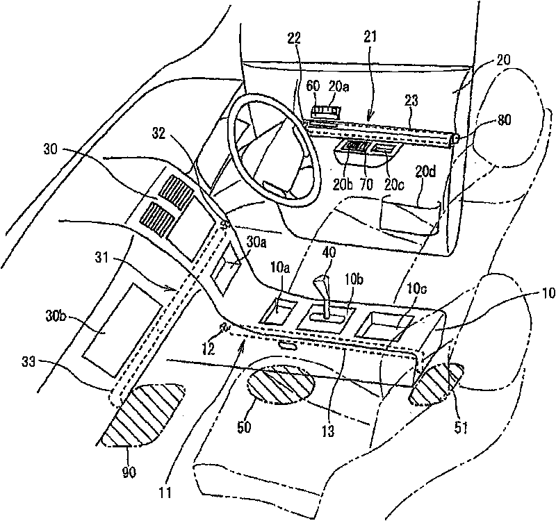
[0031] figure 1 One embodiment of the present invention is shown through FIG. 8 . figure 1 A perspective view showing a vehicle interior provided with an interior lighting device according to a preferred embodiment of the present invention.

[0032] Such as figure 1 As shown, the interior of the vehicle is provided with: a console box 10 disposed between the driver's seat and the passenger seat; a door trim 20 disposed on the inner side of the door; and an instrument panel 30 disposed on the The front side of the car. The first lighting device 11 is installed in the sub dashboard 10 , the second lighting device 21 is installed in the door trim 20 , and the third lighting device 31 is installed in the instrument panel 30 . The lighting devices 11, 21 and 31 are adapted to illuminate a plurality of areas through the light sources 12, 22 and 32, respectively.

[0033] The sub panel 10 is provided with a recessed coin box 10a, a shift panel 10b for indicating the position o...


PUM


Abstract

A vehicle interior lighting device includes a light source disposed in a vehicle, and a rod-shaped light guiding member including an one end face through which light emitted from the light source is inputted a transparent material, and a transparent material for guiding the inputted light from the one end face to an other end in an axis direction of the rod-shaped light guiding member. The rod-shaped light guiding member includes a first light radiation section for radiating light in a direction perpendicular to the axis direction according to a first illumination pattern to illuminate a first irradiated area in the vehicle, and a second light radiation section for radiating light in the direction perpendicular to the axis direction according to a second illumination pattern different from the first illumination pattern to illuminate a second irradiated area in the vehicle.

Description

[0001] This application is based on Japanese Patent Application No. 2008-251891 filed on September 29, 2008, the entire contents of which are incorporated herein by reference. technical field [0002] The invention relates to an interior lighting device for illuminating different interior areas of a vehicle. Background technique [0003] A known light-emitting device includes a light source and a rod-shaped light guide extending in the light-emitting direction of the light source and having an upper surface as a reflective surface and a lower surface as a light-emitting surface (see, for example, JP-A-2007 -179962). The light emitting device is configured such that the reflective surface of the rod-shaped light guide is provided with reflective grooves at predetermined intervals in the extending direction of the rod-shaped light guide, and among these reflective grooves, the reflective grooves close to the light source are formed on the non-reflective surface. The area outs...

Claims


Application Information

Patent Timeline
Patent Type & Authority Applications(China)
IPC IPC(8): F21S8/10F21V8/00F21W101/08F21W106/00
CPCB60Q3/0279B60Q3/005B60Q3/0209B60Q3/74B60Q3/66B60Q3/20B60Q3/217B60Q2500/30
Inventor 丸井由纪子稻垣聪
Owner TOYODA GOSEI CO LTD
Why Eureka
Try Eureka