Drive device comprising a drive shaft and a device for detecting torque

A technology of driving device and driving shaft, which is applied in the direction of measuring device, torque measurement, transportation and packaging, etc., to achieve the effect of low cost

Inactive Publication Date: 2010-05-26
SCHAEFFLER TECH AG & CO KG
View PDF6 Cites 13 Cited by
  • Summary
  • Abstract
  • Description
  • Claims
  • Application Information

AI Technical Summary

Problems solved by technology

However, there is no direct connection to the construction of the rolling bearing to describe the structure, in which the torque sensor is integrated

Method used


Image

  • Drive device comprising a drive shaft and a device for detecting torque
  • Drive device comprising a drive shaft and a device for detecting torque
  • Drive device comprising a drive shaft and a device for detecting torque

Examples


Embodiment Construction

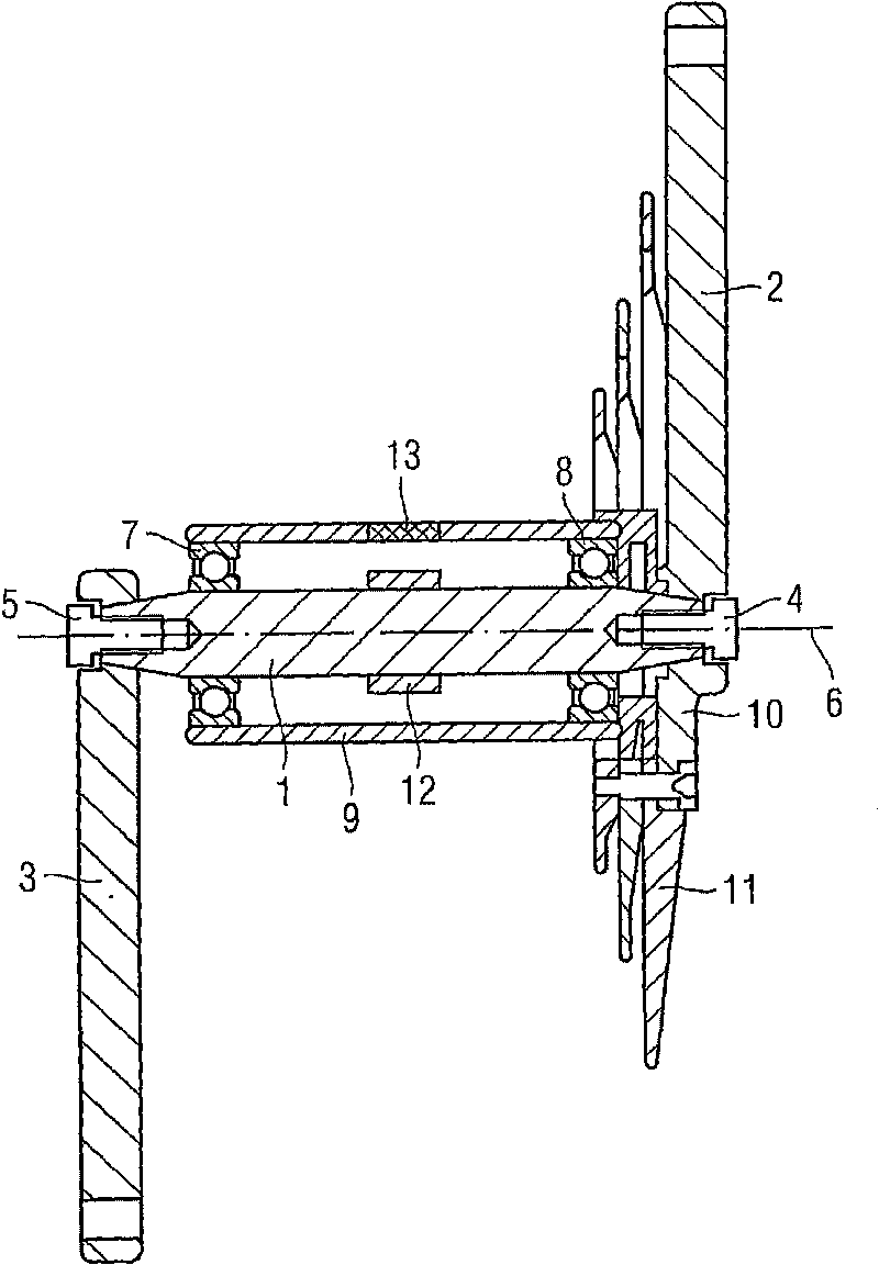
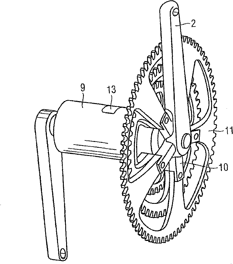
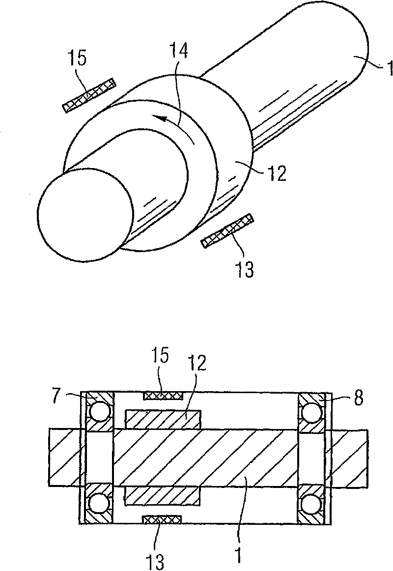
[0062] figure 1 Shown is a drive shaft 1 of a bicycle, which is connected at each of its free ends to a drive crank 2, 3 (also referred to as a pedal crank in connection with the context) via bolts 4, 5 at different angles relative to an axis 6 in the circumferential direction. Change ground to fix the connection. The shaft 1 is supported in two bearings 7 , 8 designed as ball bearings and is inserted in a protective manner in a pedal bearing housing 9 .

[0063] The component unit formed by the bearings 7 , 8 and the shaft 1 can additionally be assembled into a so-called pedal bearing bush.

[0064] The drive shaft 1 is connected via a crank star 10 to a rim or an assembly of rims 11 , which acts as an output and drives the chain of the bicycle.

[0065] Axially in the center of the shaft, a magnetostrictive body 12 in the form of a sleeve is mounted on the shaft, for example soldered or heat and sleeved. The sleeve forms part of a magnetostrictive sensor, the second part ...


PUM


Abstract

The invention relates to a drive device comprising a drive shaft (1) mounted in such a way as to rotate about an axis (6), two driving cranks (2, 3) which are connected to said shaft in an angularly rigid manner in relation to the axis in the peripheral direction, and an output element (29) which is connected to the shaft and transmits torque between the drive shaft (1) and a load element. In order to enable the measurement of the torque transmitted by means of the shaft as easily and economically as possible, the drive device is provided with at least one magnetostrictive sensor (25, 27, 30, 31) which is connected to the drive shaft in a fixed manner and axially arranged between a driving crank and the output element.

Description

technical field [0001] The invention belongs to the technical field of mechanical manufacturing and measurement. It can be used with different types of driving devices, such as bicycles, ergometers, electric bicycles or other devices that can be driven by a drive crank. The invention not only contemplates a drive, but also relates to a device that can be driven by a subsequent drive crank, in particular a bicycle, a dynamometer or an electric bicycle. Background technique [0002] In a device of this type, it is expedient to determine various variables, such as speed and the distance traveled, as in the case of a bicycle. Instantaneous speed, for example, can provide the rider with an indication of whether it makes sense to select or not select a certain gear. [0003] However, it makes sense in this type of decision to determine not only the velocity but also the momentary applied torque and thus the force loading of the components of the bicycle and the force exerted by ...

Claims


Application Information

Patent Timeline
Patent Type & Authority Applications(China)
IPC IPC(8): G01L3/10
CPCG01L3/102B60L2200/12B62M3/003Y10T74/1836
Inventor 哈拉尔德·格拉巴迈克尔·保施
Owner SCHAEFFLER TECH AG & CO KG
Why Eureka
Try Eureka