Automatic patient lifting and transferring car

A transfer vehicle and patient technology, which is applied in the direction of hospital beds, medical science, hospital equipment, etc., can solve the problems of poor automation, poor adaptability, and poor safety, and achieve high transfer efficiency, high automation, and convenient use.

Inactive Publication Date: 2010-06-02
叶强
View PDF2 Cites 16 Cited by
  • Summary
  • Abstract
  • Description
  • Claims
  • Application Information

AI Technical Summary

Problems solved by technology

[0005] The purpose of the present invention is to solve the shortcomings of poor safety, poor automation and poor adaptability in the prior art, and propose a kind of automatic lifting patient transfer vehicle

Method used


Image

  • Automatic patient lifting and transferring car
  • Automatic patient lifting and transferring car
  • Automatic patient lifting and transferring car

Examples


Embodiment Construction

[0024] The present invention will be further described below in conjunction with accompanying drawing:

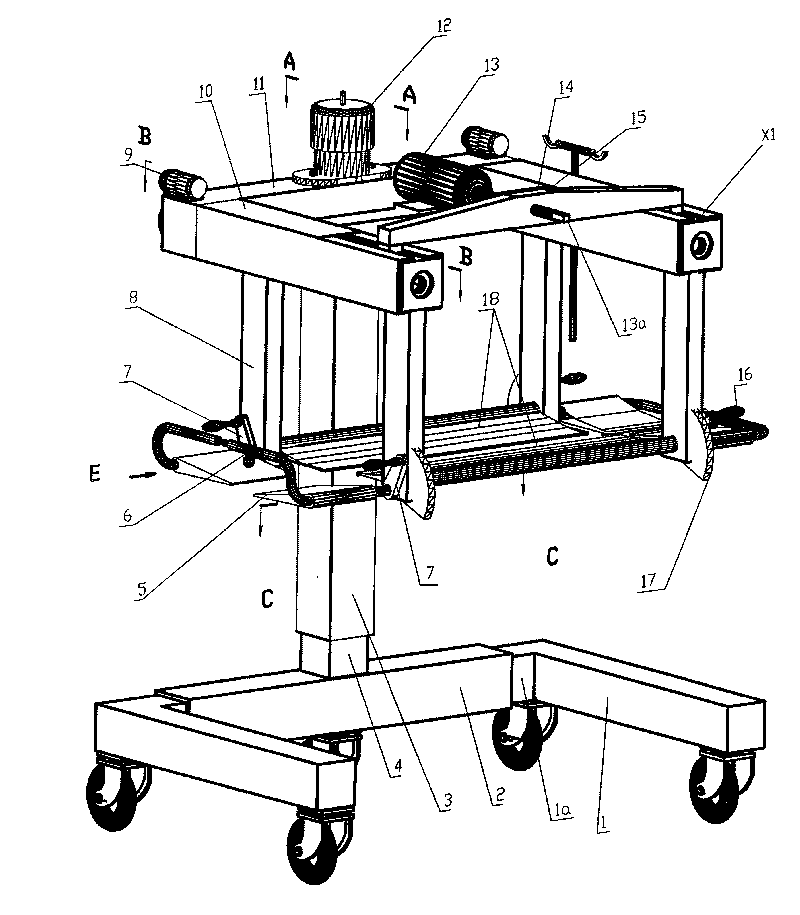
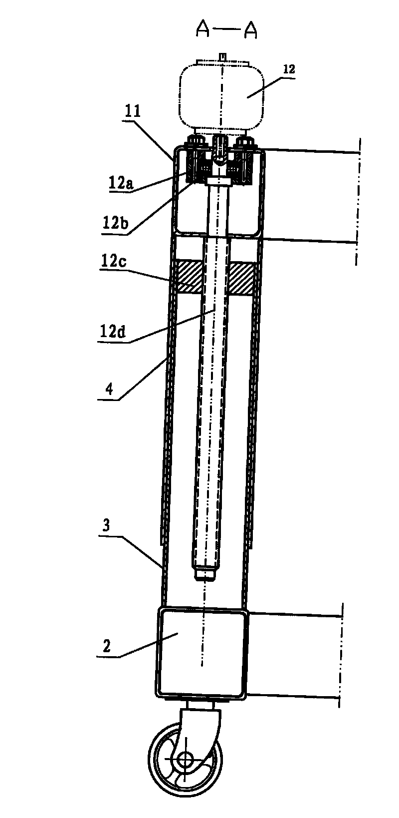
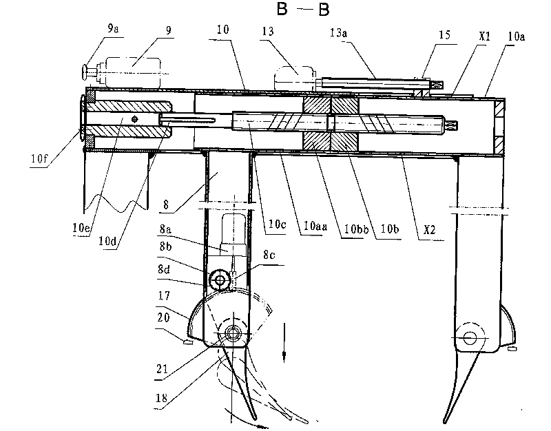
[0025] One, such as figure 1 As shown, the automatic lifting patient transfer vehicle provided by the present invention includes a concave open frame structure mobile chassis composed of square tube main beam 2 and L-shaped square tube side beams 1 on both sides, and universal wheels are arranged below the mobile chassis. A set of lifting column composed of inner pipe column 3 and outer column 4 is arranged on the mobile chassis, and a square tube-shaped crossbeam 11 is connected to the upper end of the lifting column, see figure 2 , the inner center of the beam 11 is screwed to a bearing seat 12a, wherein a plane bearing 12b is arranged, and a hanging screw 12d is set in the plane bearing 12b, and the upper end of the screw is connected to the output shaft of the motor 12 arranged on the beam 11 , the middle part of the screw rod is connected and matched with the nut 12c...


PUM


Abstract

The invention relates to an automatic patient lifting and transferring car. Both ends of a cross beam connected by an upright post are respectively connected with a longitudinal beam (10); a pair of vertical beams (8) are connected in the longitudinal beam (10); a motor (8a) and worms (8c) connected with the motor are arranged in the vertical beam and connected with a worm wheel (8b) in a matched mode; the worm wheel is coaxially connected with gears (8d) and matched with a sector gear (17) for transmission so as to drive a connection tubular axle (21) to rotate; and a main reverse turning bed (18) is fixed and connected with the tubular axle (21). Via the vertical movement of the upright post and the movement of the reverse turning bed, a downward bottom shoveling and collecting movement is produced, so that the patient is transferred to a pair of reverse turning beds, and then the upright post rises, and the patient is transferred. Each motor can be accurately controlled via a microcomputer or PLC and automatically and efficiently complete different kinds of movements. The transferring car is suitable for all sick beds and for transferring patients among the large scale equipment with same width such as a CT machine and an operating table, and has the advantages of high degree of automation, high security, high transfer efficiency, convenient use and the like.

Description

Technical field: [0001] The invention relates to a medical device, in particular to a medical automatic lifting stretcher type patient transfer vehicle, which is especially suitable for a transportation device designed for critically ill patients, mobility-impaired patients, or surgical anesthetized and unconscious patients who need to be transferred. Background technique [0002] With the rapid development of medical care and the continuous expansion of the scope of medical insurance, people's living standards and income levels have gradually increased, the number of patients seeking medical treatment and surgery has increased, and the workload of transporting critically ill and surgical patients has increased. trouble and pain. Nursing long-term bedridden and paralyzed patients turning over and cleaning the bed is a difficult job, and it is also a difficult problem that people have always hoped to solve. [0003] Through retrieval, a kind of lifting stand-up nursing devic...

Claims


Application Information

Patent Timeline
Patent Type & Authority Applications(China)
IPC IPC(8): A61G7/14
Inventor 叶强姚方孝杨其敏李萌叶明
Owner 叶强
Why Eureka
Try Eureka