No-fan flame multilayer oxygen supply energy saving burner

A technology without fans and burners, applied in burners, gas fuel burners, combustion methods, etc., can solve the problems of insufficient combustion of gas, taken away immediately after use, and no combustion of gas, and achieve smooth drainage and windproof performance. Excellent, energy saving effect

Inactive Publication Date: 2010-06-02
施央君 +1
View PDF0 Cites 12 Cited by
  • Summary
  • Abstract
  • Description
  • Claims
  • Application Information

AI Technical Summary

Problems solved by technology

When cooking food in a small pot, the burner needs to be adjusted to a low fire state, but when the traditional burner is adjusted to a low fire, the combustion effect is often poor, that is, the gas is not completely burned, resulting in a waste of energy
When it is necessary to increase the combustion effect, the traditional burner usually uses a fan to cooperate with it to form a fan burner, but the fan burner usually has the following defects: (1). The noise is generally greater than 75 decibels, resulting in noise pollution; (2), the exhaust system needs to be enlarged, and the gas in the outer edge of the flame is discharged before it is completely burned, resulting in exhaust pollution; (3), in order to ensure the combustion effect, it is necessary to increase the The gas volume is matched with the corresponding wind speed and flow rate. If the wind speed and flow rate are small, the gas combustion will be insufficient, resulting in energy waste; if the wind speed and flow rate is small, the heat energy will be taken away before it is fully utilized, resulting in heat energy loss. The constant range of use is small.

Method used


Image

  • No-fan flame multilayer oxygen supply energy saving burner
  • No-fan flame multilayer oxygen supply energy saving burner
  • No-fan flame multilayer oxygen supply energy saving burner

Examples


Embodiment Construction

[0017] The present invention will be further described below in conjunction with specific drawings and embodiments.

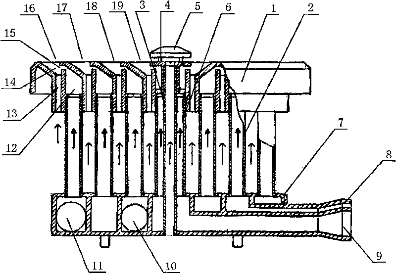
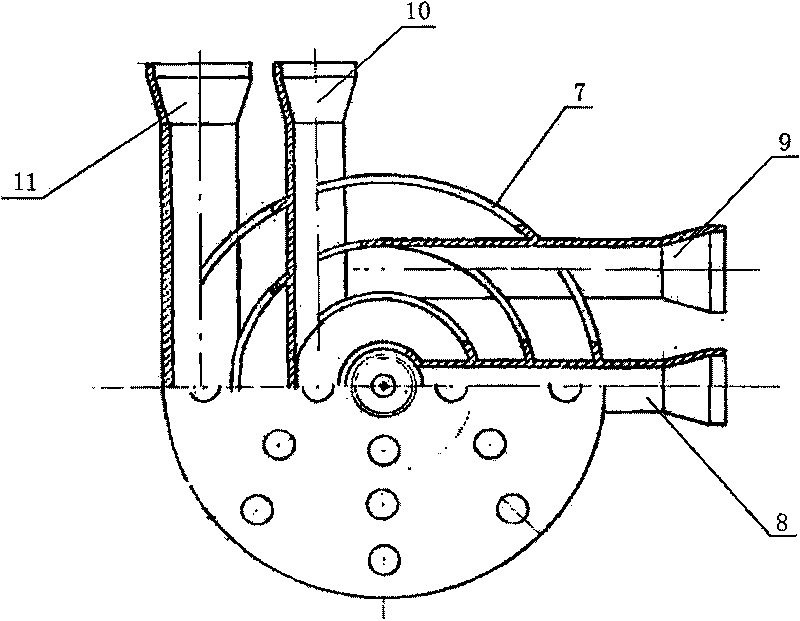
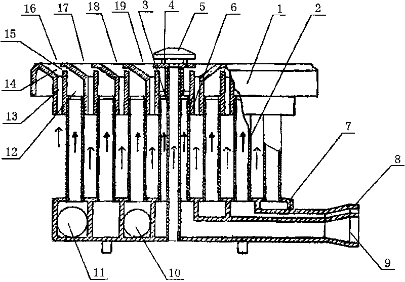
[0018] Such as figure 1 , figure 2 As shown, the present invention is mainly composed of a combustion disk 1, a gas pipe 2, an oxygen supply pipe 3, a top cover 5, an intake sleeve 6 and a flow divider 7; the upper part of the combustion disk 1 is sequentially provided with a central combustion chamber 19 from the center 1, the first stage outer combustion chamber 18, the second stage outer combustion chamber 17 and the third stage outer combustion chamber 16, the lower part of the burning disc 1 is provided with the central combustion chamber 19, the first stage outer combustion chamber 18, the second stage outer combustion chamber respectively Combustion chamber 17 and the connection hole that the third stage outer combustion chamber 16 communicates correspondingly; On the diverter 7, be provided with central air intake hole, first stage outer air inlet hol...


PUM


Abstract

The invention relates to a no-fan flame multilayer oxygen supply energy saving burner, comprising a combustion tray and a shunt, wherein the upper part of the combustion tray is successively provided with a central combustion chamber and at least one stage of external combustion chamber from center to periphery, and the lower part of the combustion tray is provided with connecting holes which are respectively and correspondingly communicated with the central combustion chamber and at least one stage of external combustion chamber; the shunt is successively provided with a central air inlet and at least one stage of external air inlet from center to periphery, the central air inlet corresponds to the connecting hole of the central combustion chamber and is connected with the connecting hole of the central combustion chamber by an air inlet sleeving; the external air inlet corresponds to the connecting holes of each stage of external combustion chamber on the combustion tray one by one and is connected with the connecting holes of each stage of external combustion chamber by a gas pipe; gas is respectively led into the central air inlet and the external air inlet by a central inlet pipe and an external inlet pipe; the center of the combustion tray is provided with a midstream ring in which an oxygen supply pipe is spliced; and the oxygen supply pipe is installed in the air inlet sleeving and downwards passes through the shunt. The invention has reasonable and artful structure, energy saving, no noise pollution, sufficient combustion and wide application range.

Description

technical field [0001] The invention relates to an accessory part used on a gas cooker such as a gas cooker, in particular to an energy-saving burner without fan flame and multi-layer oxygen supply. Background technique [0002] The burner is the most important component in a gas hob. When cooking food in a small pot, the burner needs to be adjusted to a low fire state, but when the traditional burner is adjusted to a low fire, the combustion effect is often poor, that is, the gas is not completely burned, resulting in a waste of energy. When it is necessary to increase the combustion effect, the traditional burner usually uses a fan to cooperate with it to form a fan burner, but the fan burner usually has the following defects: (1). The noise is generally greater than 75 decibels, resulting in noise pollution; (2), the exhaust system needs to be enlarged, and the gas in the outer edge of the flame is discharged before it is completely burned, resulting in exhaust pollution...

Claims


Application Information

Patent Timeline
Patent Type & Authority Applications(China)
IPC IPC(8): F23D14/22F23D14/58
Inventor 施央君孙凤枝
Owner 施央君
Why Eureka
Try Eureka