Laser image module and non-contact type measurement device using same

An image module and laser technology, applied in the direction of measuring devices, optical devices, instruments, etc., can solve the problems of plastic deformation of curved plate parts, increase the difficulty of precise processing and measurement, and achieve the effect of low manufacturing cost

Active Publication Date: 2010-06-02
SAMSUNG HEAVY IND CO LTD
0 Cites 4 Cited by

AI-Extracted Technical Summary

Problems solved by technology

Therefore, various factors, such as ambient temperature and worker negligence, may cause plastic deformation o...

Abstract

The invention relates to a laser image module and a non-contact type measurement device using the same, in particular to a device for measuring the shape of an object by a non-contact method and a laser image module used in the device. According to some aspects of the invention, a cross laser beam radiates a laser generator on the object; and a pair of cameras which photograph the laser beam image of the cross laser beam radiating the object can be integrally installed on a single fixing piece, thereby realizing the measurement of the object without any rotation, obtaining distortionless three-dimension shape measurement data, and minimizing the cost of the non-contact measurement device at the same time.

Application Domain

Using optical means

Technology Topic

Measurement deviceContact method +3

Image

  • Laser image module and non-contact type measurement device using same
  • Laser image module and non-contact type measurement device using same
  • Laser image module and non-contact type measurement device using same

Examples

  • Experimental program(1)

Example Embodiment

[0034] Hereinafter, certain embodiments of the present invention will be described in more detail with reference to the accompanying drawings. In the description of the present invention, when it is considered that certain detailed descriptions of related technologies may unnecessarily dilute the essence of the present invention, these detailed descriptions are omitted.
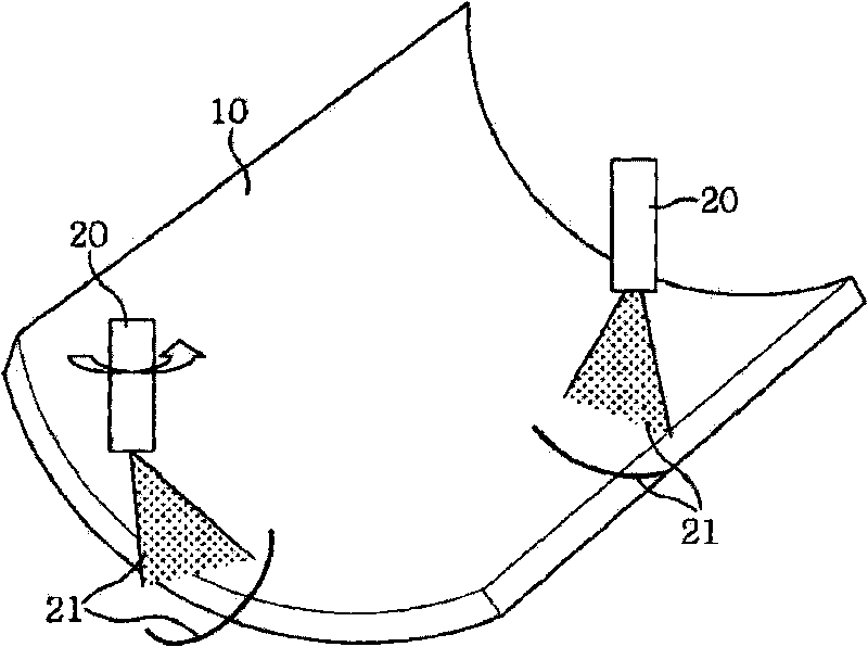
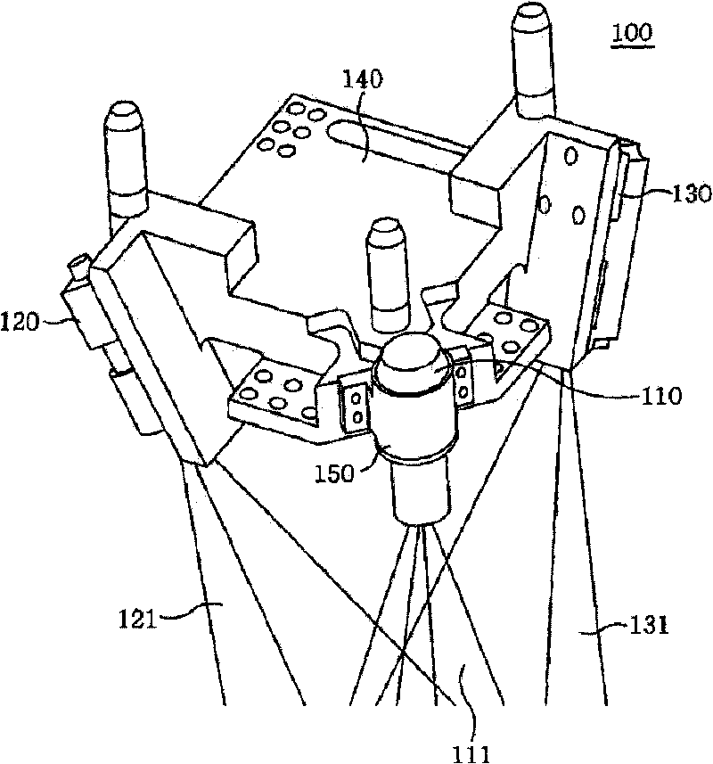
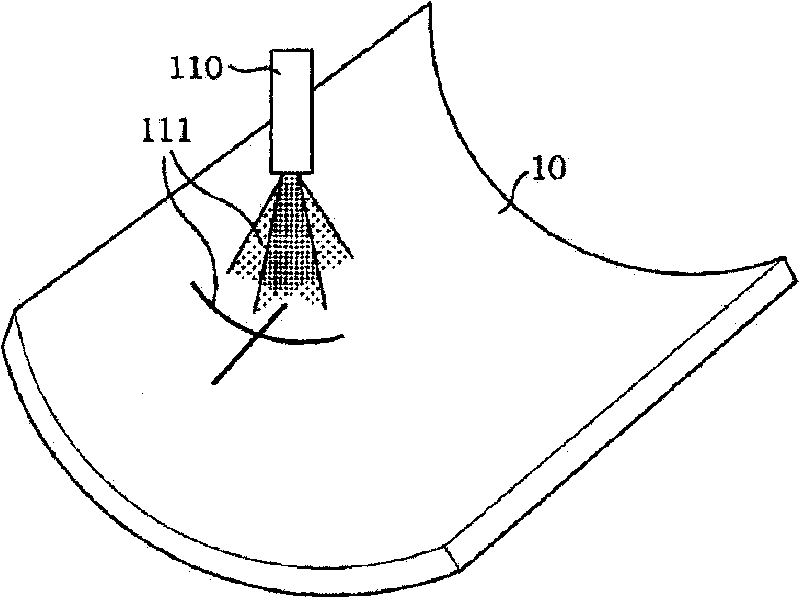
[0035] figure 2 It is a laser imaging module for a non-contact measuring device according to one aspect of the present invention. Such as figure 2 As shown, the laser imaging module 100 according to one aspect of the present invention includes: a laser generator 110 for irradiating a cross-shaped laser beam 111 on the object to be measured; a pair of cameras 120 and 130 for irradiating the object to be measured The laser beam images 121, 131 are photographed; and a single fixing member 140 on which the laser generator 110 and the camera pair 120, 130 are mounted as a whole. The laser generator 110 may be installed in the housing 150, which is connected to the fixing member 140 as a whole, so that the laser generator 110 may rotate around the intersection of the cross-shaped laser beam 111. The camera pair 120, 130 is mounted on the fixing member 140 so that the first imaginary line connecting the center of the first camera 120 and the center of the laser generator 110 and the second imaginary line connecting the center of the second camera 130 and the center of the laser generator 110 The imaginary line is vertical.
[0036] Using the laser imaging module 100 structured as described above, such as image 3 As shown, the cross-shaped laser beam 111 is irradiated by the laser generator 110 onto the object to be measured, that is, the curved plate 10. In this way, the cross laser beam 111 emitted from the laser generator 110 can be regarded as a vertical line beam and a horizontal line beam separately, wherein one of the camera pairs 120, 130 can be used to obtain the laser beam image from the vertical line beam, and the other camera can be used. To obtain the laser beam image from the horizontal beam. In doing so, a selective filtering operation can be performed on one of the vertical wire harness portion and the horizontal wire harness portion.
[0037] The filtering can be performed by placing a filtering device on the path of the image traveling to the cameras 120 and 130, or performing a filtering operation on the image data obtained by the cameras 120 and 130. The present invention will be explained by an embodiment employing the latter method of filtering image data. If in one of the camera pairs 120 and 130, the vertical line beam of the cross laser beam 111 is obtained as the vertical image part and the horizontal line beam is obtained as the horizontal image part, then in the other camera, the vertical line beam of the cross laser beam 111 is obtained as The horizontal image part is obtained and the horizontal wire harness is obtained as the vertical image part.
[0038] Therefore, when the image data obtained by the camera pairs 120 and 130 are filtered, the vertical image portion will be filtered and removed from the camera pairs 120 and 130 respectively to generate the three-dimensional shape measurement data of the curved plate 10. Will refer to later Figure 4 The filtering process is explained in more detail.
[0039] By installing the laser generator 110 in the housing 150 connected to the fixing member 140 as a whole, the laser generator 110 can be rotated around the intersection of the cross-shaped laser beam 111, and the laser generator 110 can be rotated to form a cross-shaped laser. The optical axes of the vertical and horizontal beams of the beam 111 are aligned with the optical axes of the cameras 120 and 130.
[0040] Figure 4 It is a block diagram showing a non-contact measurement device according to one aspect of the present invention.
[0041] Such as Figure 4 As shown, the non-contact measurement device according to one aspect of the present invention includes: a laser imaging module 100, which includes a laser generator 110, a camera pair 120, 130, etc.; an image filtering unit 210, which can filter the data obtained by the cameras 120, 130 Image data to remove the vertical image part; measurement data generation unit 220, which extracts a certain measurement point data from the processed image data filtered by the image filtering unit 210, and expresses the measurement point data as a curved surface through model operations to generate three-dimensional shape measurement Data; and a control unit 230 that manages the operation of the laser generator 110, the camera pair 120, 130, the image filtering unit 210, and the measurement data generating unit 220.
[0042] In the non-contact measurement device, the first imaginary line connecting the center of the first camera 120 and the center of the laser generator 110 is perpendicular to the second imaginary line connecting the center of the second camera 130 and the center of the laser generator 110. Therefore, if, for example, in the first camera 120, the vertical line beam of the cross laser beam 111 is obtained as the vertical image part and the horizontal line beam is obtained as the horizontal image part, then, in the second camera 130, the vertical line beam of the cross laser beam 111 is obtained as the horizontal The image part is obtained and the horizontal harness is obtained as the vertical image part.
[0043] Then, under the control of the control unit 230, the image filtering unit 210 filters and removes the vertical image portion when filtering the image data obtained by the cameras 120 and 130. The measurement data generation unit 220 extracts certain measurement point data from the filtered image data under the control of the control unit 230, and then expresses the measurement point data as a curved surface through model operation to generate three-dimensional shape measurement data.
[0044] Although the spirit of the present invention has been described in detail based on a specific embodiment, this embodiment is only for illustrative purposes and does not limit the present invention. It should be understood that those of ordinary skill in the art can make changes or modifications to the embodiments without departing from the scope and spirit of the present invention as described in the appended claims.

PUM

no PUM

Description & Claims & Application Information

We can also present the details of the Description, Claims and Application information to help users get a comprehensive understanding of the technical details of the patent, such as background art, summary of invention, brief description of drawings, description of embodiments, and other original content. On the other hand, users can also determine the specific scope of protection of the technology through the list of claims; as well as understand the changes in the life cycle of the technology with the presentation of the patent timeline. Login to view more.

Similar technology patents

Preparation method and device of natural gas hydrate with uniform high saturability in sediment

ActiveCN103528865AReduce high pressure requirementslow manufacturing cost
Owner:GUANGZHOU INST OF ENERGY CONVERSION - CHINESE ACAD OF SCI

Herringbone gear shaft and production method thereof

ActiveCN102937173Alow manufacturing costEfficient detection
Owner:WUXI WEIFU CHINA ITAL GEAR

Full-automatic electric cooker

InactiveCN103815770Alow manufacturing costRow rice clean
Owner:江门市骏万电器制造有限公司

Classification and recommendation of technical efficacy words

  • low manufacturing cost

Exercise equipment

InactiveUS6942605B1low manufacturing costlow price of sale
Owner:SUKHOVITSKY FELIKS

Compliance partitioning in testing of integrated circuits

InactiveUS20080061808A1low manufacturing costgood impedance control
Owner:INNOCONNEX

Inkjet recording apparatus

InactiveUS20050237352A1low manufacturing costfine image quality
Owner:KONICA MINOLTA MEDICAL & GRAPHICS INC
Why Eureka
Try Eureka