High temperature resistant dry bag-type dust remover

A bag filter, high temperature resistant technology, applied in chemical instruments and methods, dispersed particle separation, dispersed particle filtration, etc., can solve the problem of increasing the workload of repairing and replacing bags, short service life of filter bags, and increasing use and maintenance costs, etc. problems, to reduce the use and maintenance costs, reduce the workload of repair and replacement, and speed up the discharge

Inactive Publication Date: 2010-06-09
长沙奥邦环保实业有限公司
View PDF1 Cites 2 Cited by
  • Summary
  • Abstract
  • Description
  • Claims
  • Application Information

AI Technical Summary

Problems solved by technology

The disadvantage of this "large blast furnace gas dry-type bag filter" is that because the filter bag is installed in a closed cylinder, the filter bag is easily damaged under the working condition of high-temperature dust airflow, and the high-temperature resistance is poor. The service life of the cloth bag is short, which increases the workload of repairing and replacing the cloth bag, and increases the cost of use and maintenance

Method used


Image

  • High temperature resistant dry bag-type dust remover
  • High temperature resistant dry bag-type dust remover
  • High temperature resistant dry bag-type dust remover

Examples


Embodiment 1

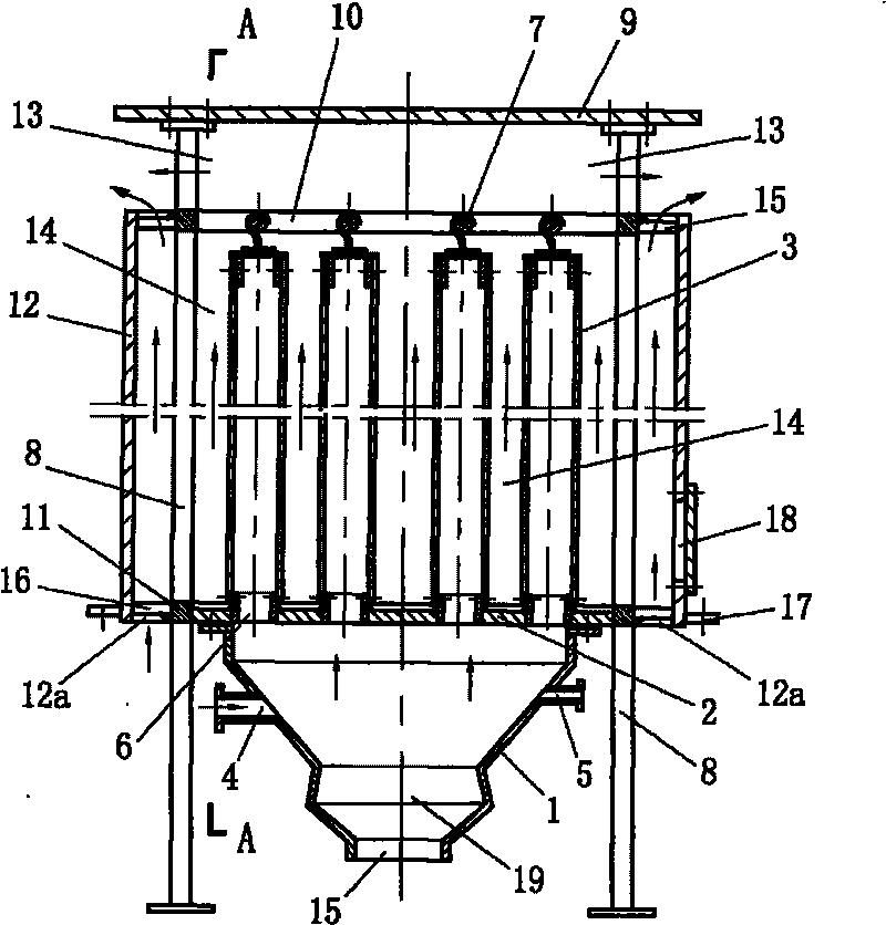
[0016] Example 1, see figure 1 , figure 2 .

[0017] The structure of embodiment 1 includes an ash hopper 1, an air distribution plate 2, several filter bags 3, an air inlet 4, and a dust-cleaning airflow hole 5, and the ash hopper 1 of this example is one; the upper part of the ash hopper 1 and the air distribution plate 2 is a sealed connection, with ash outlet 15 at the lower part; airflow holes 6 on the airflow distribution plate 2, the upper ends of the filter cloth bags 3 are respectively connected to the corresponding rods 7, and the lower ends of the filter cloth bags 3 are connected to the airflow holes 6 of the airflow distribution plate 2 The place is a sealed connection, the distribution and connection mode of the filter bag 3, in addition to the diagram and the aforementioned form, there are also a variety of variable settings; the air inlet 4 and the airflow hole 6 on the airflow distribution plate 2 It communicates with the inner cavity of the filter bag 3, t...

Embodiment 2

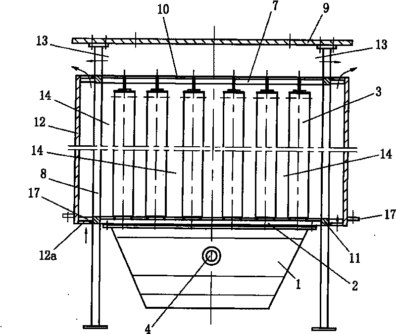
[0021] Example 2, see Figure 4 , Figure 5 .

[0022] This example is different from Embodiment 1 in that the number of filter bags 3 in the open cylinder 12 is larger than that in Embodiment 1, and two ash hoppers 1 are provided, and each ash hopper is connected to the filter bag in the cylinder 12. Part of the filter bag 3 corresponds, and each ash hopper and the corresponding filter bag 3 can be regarded as a unit; according to the number of filter bags 3, the ash hopper 1 can also be three or more to meet a larger amount When there are at least two ash hoppers 1, an air inlet channel 20 communicating with the inside of the cylinder 12 can be set between the ash hoppers, and the natural wind enters through the air inlet channel 20, which is open up and down. The inside of the cylinder 12 is to meet the cooling of the filter bag 3 in the middle, so as to effectively improve the reliability of the filter bag operation, reduce the damage to the filter bag caused by high tem...


PUM


Abstract

The invention discloses a high temperature resistant dry bag-type dust remover. A dust hopper (1) is connected with an airflow distribution plate (2); airflow holes (6), an air inlet (4) and a deashing airflow hole (5) are formed on the air-flow distribution plate (2); the upper ends of a plurality of filter bags (3) are connected to corresponding rods (7), and the lower ends of the filter bags are connected with the airflow holes (6) of the airflow distribution plate (2); the air inlet (4), the deashing airflow hole (5) and an inner cavity of the dust hopper (1) are communicated with the airflow holes (6) on the airflow distribution plate (2) and inner cavities of the filter bags (3); a top plate (9) is arranged on a frame (8), and the airflow distribution plate (2) is connected with a member (11) on the lower part of the frame (8); the filter bags (3) are positioned in a cylinder (12) of which the upper part and the lower part are open; air overflow channels (14) of the filter bags (3) are communicated with an airflow outlet (13); an upper opening of the cylinder (12) is communicated with a cavity between the upper opening and the top plate and forms the air-flow outlet (13); and an airflow channel (12a) communicated with the atmosphere is arranged in the lower opening.

Description

Technical field [0001] The invention relates to a device for separating dispersed dust particles from the air, in particular to a high temperature-resistant dry bag type dust collector. Background technique [0002] The utility model patent specification No. 200720005346.6 published on January 23, 2008 with the authorization announcement number CN201008774Y discloses a "large blast furnace gas dry bag filter". The dust collector consists of a closed cylinder and an ash hopper. The upper end of the ash hopper is connected with the lower end of the cylinder as a whole. There is a grille plate at the upper end of the cylinder, and an air distribution plate at the lower end. There are several filter bags inside the cylinder. The upper end is connected with the grille, the cylinder body is provided with an air inlet, the air inlet communicates with the inner cavity of the ash hopper, the lower opening of the filter bag communicates with the inner cavity of the ash hopper, and the...

Claims


Application Information

Patent Timeline
Patent Type & Authority Applications(China)
IPC IPC(8): B01D46/02
Inventor 段若新王占国莫建炎
Owner 长沙奥邦环保实业有限公司
Why Eureka
Try Eureka