

Tool positioning device
A positioning device and tool technology, applied in positioning devices, manufacturing tools, metal processing equipment, etc., can solve the problems of shallow processing depth and poor processing, so as to prevent chips from hanging on the tool, improve processing accuracy and work efficiency Effect
- Summary
- Abstract
- Description
- Claims
- Application Information
AI Technical Summary
Problems solved by technology
Method used
Image

Examples
no. 1 Embodiment approach
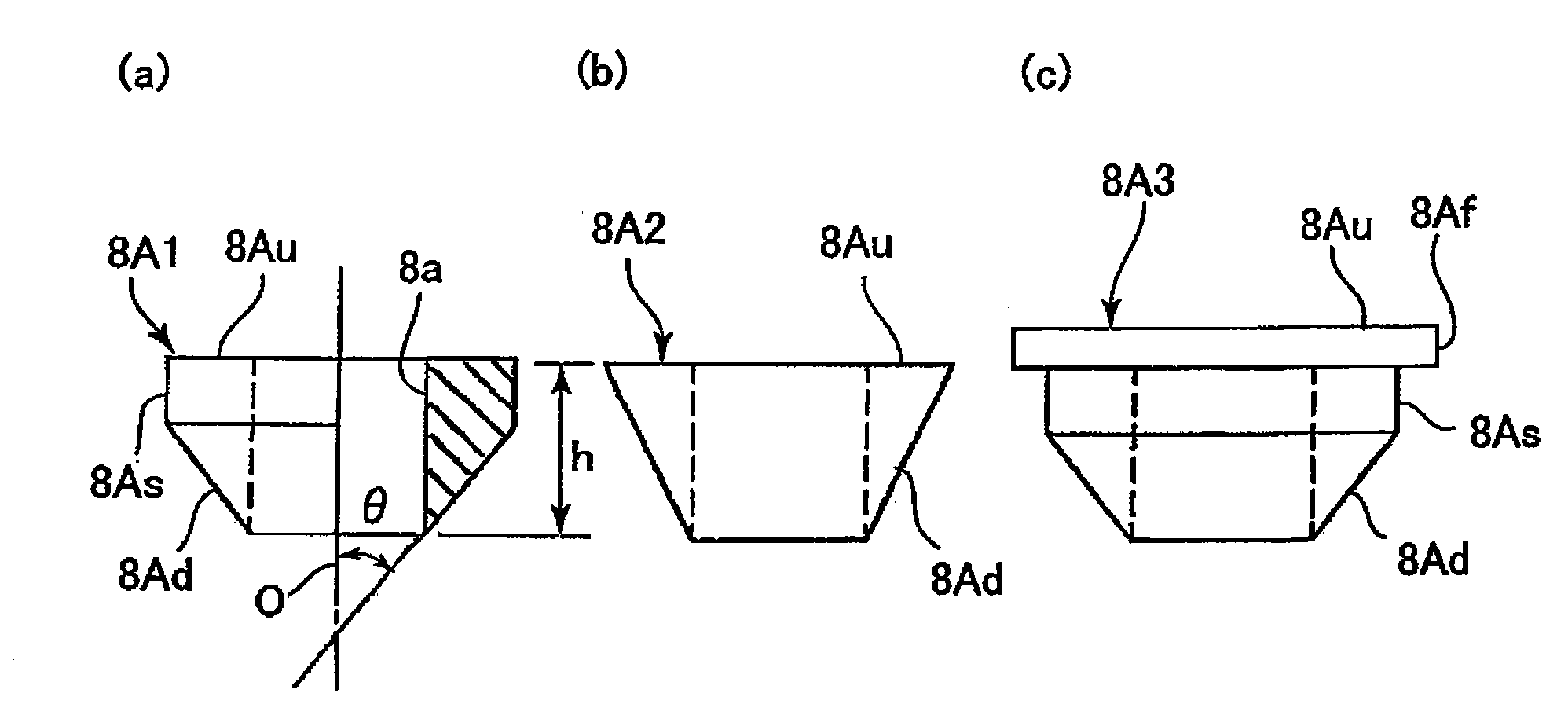
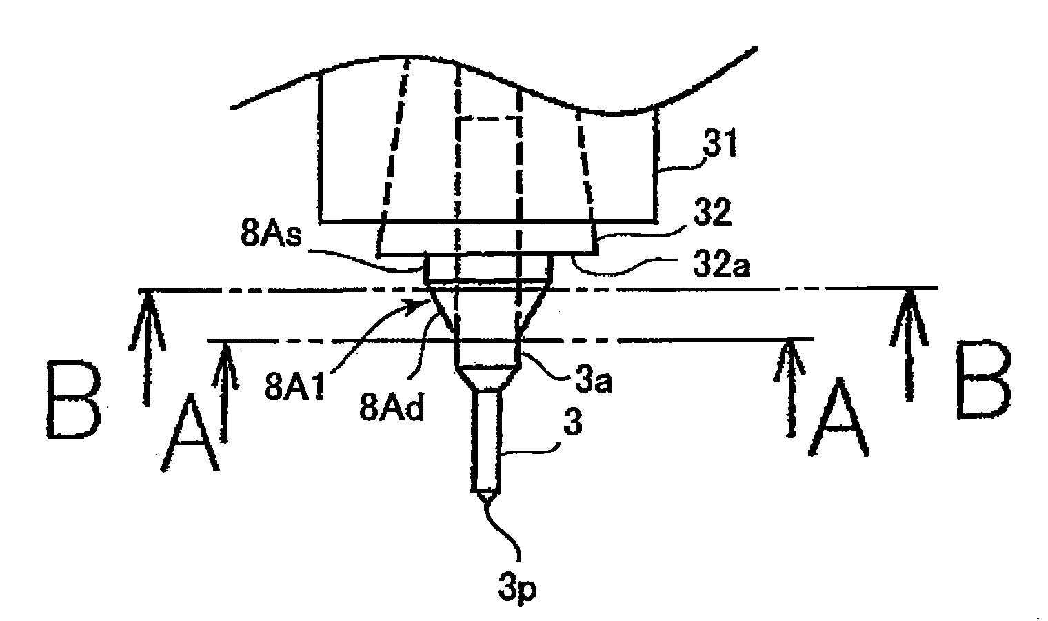
[0046] figure 1 It is a block diagram of a collar as a tool positioning device according to the first embodiment of the present invention, (a) is a partial front sectional view of the collar, and (b) and (c) are front views of modified examples of the collar. figure 2 It is an explanatory diagram showing the state in which the drill with the collar clamped is held in the collet.
[0047] Such as figure 1 As shown, in the collar 8A1 according to the first embodiment, a drill 3 ( figure 2 ) The hollow cylindrical shape of the hole 8a fitted is a tool positioning device for clamping on the drill 3 and positioning the head end 3p of the drill 3. The collar 8A1 is formed of, for example, hard synthetic resin, and the diameter of the hole 8a provided in the center is formed to be slightly smaller than the shank 3a of the drill 3 ( figure 2 ) of the outer diameter. As a result, the collar 8A1 in which the shank 3a of the drill 3 is pressed into the hole 8a is integrated with...
no. 2 Embodiment approach
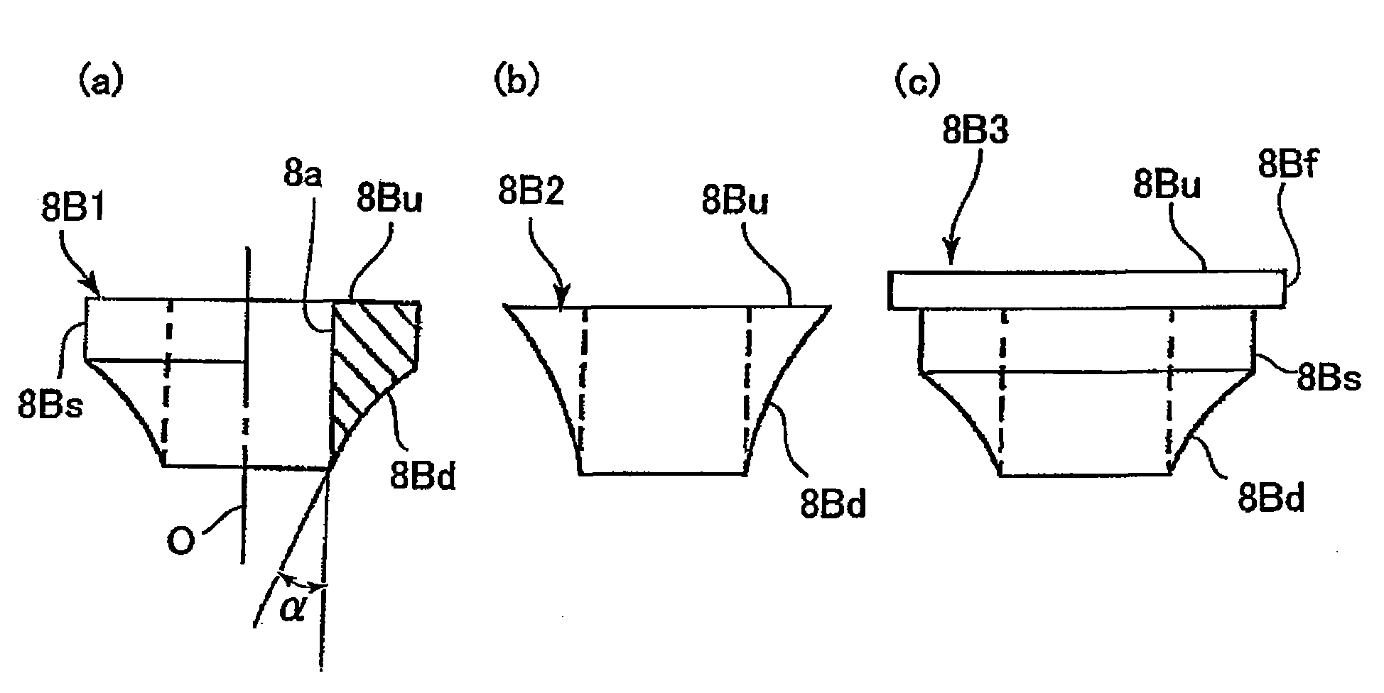
[0060] image 3 It is a block diagram of a collar as a tool positioning device according to the second embodiment of the present invention, (a) is a front partial sectional view of the collar, and (b) and (c) are front views of modified examples of the collar.
[0061] also, image 3 (a), (b), (c) in figure 1 (a), (b), (c) correspond.
[0062] On the upper end of the axis O direction of the collar 8B1, a head end 32a ( figure 2 ) of the upper end surface 8Bu as a flat surface, the upper end surface 8Bu is formed perpendicular to the axis O of the hole 8a. The lower end of the collar 8B1 in the axis O direction is the outer edge of the hole 8a, and the side surface of the collar 8B1 has an inclined surface 8Bd that is connected to the lower end of the axis O direction, that is, the outer edge of the hole 8a and expands upward from the outer edge of the hole 8a. A peripheral side surface 8Bs parallel to the axis O extending upward from the upper end of the inclined surface...
no. 3 Embodiment approach
[0069] Figure 4 It is a structural view of a collar as a tool positioning device according to a third embodiment of the present invention, (a) is a front partial sectional view of the collar, and (b) and (c) are front views of modified examples of the collar.
[0070] in, Figure 4 (a), (b), (c) correspond to image 3 (a), (b), (c) of.
[0071] The head end 32a ( figure 2 ) of the upper end surface 8Cu as a flat surface formed perpendicular to the axis O of the hole 8a. The lower end of the ring sleeve 8C1 in the direction of the axis O is the outer edge of the hole 8a, and the side surface of the ring sleeve 8C1 has an inclined surface 8Cd that is connected to the outer edge of the hole 8a and expands upward from the lower end in the axis O direction, and an upper end of the inclined surface 8Cd. The peripheral side surface 8Cs parallel to the axis O extending upward.
[0072] The inclined surface 8Cd of the collar 8C1 is formed as a convex curved surface swollen towar...
PUM
 Abstract
Description
Claims
Application Information