Nailing machine structure

A nailing machine and nailing cartridge technology, applied in the field of nailing machines, can solve the problems of user application limitation, danger, loss, etc., and achieve the effects of improving convenience, safety, and convenience.

Inactive Publication Date: 2012-05-30
JANN YEI IND
View PDF0 Cites 0 Cited by
  • Summary
  • Abstract
  • Description
  • Claims
  • Application Information

AI Technical Summary

Problems solved by technology

[0005] But this existing nailing machine mainly utilizes the front guide piece 15 that can be selectively buckled and separated with the body 10 seat frame 12 to change the width of the nail opening, so the fixing method of its main engagement is to utilize the first guide piece 15 of the front guide piece 15. , the first front and rear buckle grooves 171, 172 or the second rear and front buckle grooves 182, 181 of the two extension pieces 161, 162, and the front guide piece 15 is located at the nailing movement part 101 of the body 10, and its inside is provided with In addition to the nailing piece 11 that can be powerfully fired downwards, there is also a safety device to prevent misoperation and a hook-lifting structure of the pressing handle (not shown in the figure). The relatively fixed front guide piece 15 is easy to loosen and forms an unstable situation. Therefore, the first front and rear buckle grooves 171, 172 of the first and second extension pieces 161, 162 and the second back and front buckle The grooves 182, 181 need to be tightly matched with the front and rear buckle blocks 131, 132 of the frame 12 of the body 10, so as to avoid the loosening of the front guide piece 15 during the nailing process, but this will only increase the pulling out and installation of the front guide piece 15. Difficulty, causing inconvenience in use; and under long-term use, the front guide piece 15 will still loosen due to continuous strong vibration, and then there may be a danger; Dropped and lost, causing great trouble to the user's application; in addition, the existing nailing machine can only be used for nail bodies with two different wire diameter specifications, which also greatly restricts the user's application
Therefore, this existing nailing machine has a place to be urgently improved in terms of structural stability, convenience of use, safety of nailing, loss of access, multi-standard versatility, etc.

Method used


Image

  • Nailing machine structure
  • Nailing machine structure
  • Nailing machine structure

Examples


Embodiment Construction

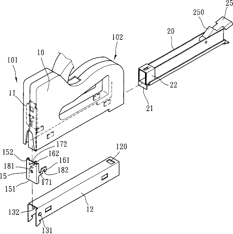
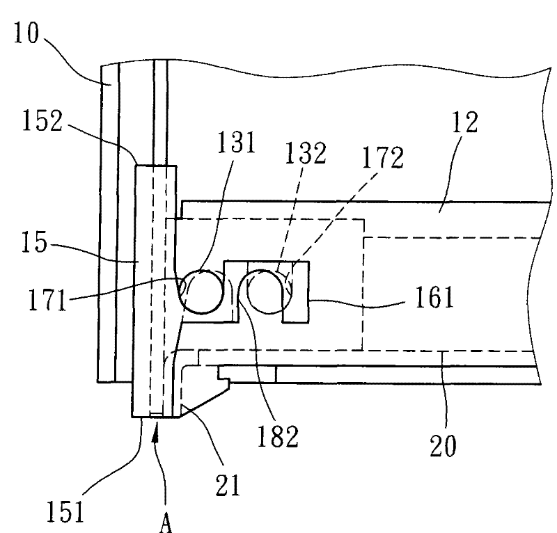
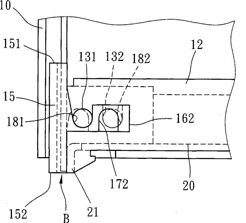
[0077] For the detailed composition of the nailing machine of the present invention, please refer to Figure 4 to Figure 8 As shown, the nailing machine generally includes a body 30, a nail magazine 40 and a dialing member 50, wherein the nail magazine 40 can be slidably embedded in the bottom edge of the body 30, and the dialing member 50 on the body 30 can change the nail magazine 40 positioning position;

[0078] The aforementioned machine body 30 is made up of two opposite shells, and the two ends of the machine body 30 respectively have a nailing moving part 301 and a nail box entry and exit part 302, wherein the nailing moving part 301 has a downward powerful firing The nail plate, related driving components, etc., and the nail box inlet and outlet part 302 can be used for sliding in and selectively positioning the aforementioned nail box 40 for accommodating the nail body. Remove the horizontal frame 31 below the mouth, and the body 30 is provided with a front guide pi...


PUM


Abstract

The invention discloses a nailing machine structure, comprising a machine body, a nail box, and an allocating piece, wherein two ends of the machine body are respectively provided with a nail beating moving part and a nail box inlet-outlet part; the nail beating moving part is internally provided with a nail beating sheet capable of forcibly cocking downwards; the bottom face of the machine body is provided with a frame seat; the nail beating moving part at the front end of the machine body is also internally provided with a front guide sheet for guiding the nail beating sheet; the nail box is selectively embedded in the frame seat of the machine body; a rear guide sheet capable of keeping specific space with the front guide sheet is arranged on a downward protrusion of the bottom edge atthe front end of the nail box; the nail box is provided with a nail pushing piece for continuously pushing nail bodies forward in a sliding way; the rear end of the nail box is provide with a pressing buckle piece which can automatically reset upwards, the pressing buckle piece is provided with an embedding clamping groove; the allocating piece is arranged on the nail box inlet-outlet part of themachine body and corresponds to the pressing buckle piece of the nail box; the allocating piece selectively embeds and tugs the embedded part of the pressing buckle piece of the nail box; the embedded part is formed by at least two embedding clamping blocks which can be embedded into the embedding clamping groove of the pressing buckle piece oppositely; and the width of the distance between each embedded block butting end face and an allocating central line is different. The invention improves the convenience of application, and achieves structural stability.

Description

technical field [0001] The invention relates to a nailing machine, in particular to a nailing machine structure that is stable, safe, convenient and not lost, and can be used for nails with multiple specifications and different wire diameters. Background technique [0002] At present, the nail bodies used for nailing machines are affected by the supply and demand of different countries and regions, and the wire diameters of the nail bodies are not the same. The diameter of the nail body accounts for about 70% to 80% of the total weight. As for Europe, it is just the opposite. 30%, and because the nailing machine uses the nailing piece in the nailing moving part of the front edge of the machine body to forcefully drive the nail body out of the nail outlet, the nail outlet of the nailing machine should be The width is usually a single specification, that is, it can only be applied to nails with a single wire diameter. However, although there are specifications marked on the n...

Claims


Application Information

Patent Timeline
Patent Type & Authority Patents(China)
IPC IPC(8): B25C1/00
Inventor 陈东益李永顺
Owner JANN YEI IND
Why Eureka
Try Eureka