Novel ratchet compensating device

A compensation device and ratchet technology, applied in the direction of overhead lines, etc., can solve the problems that it is difficult to meet the requirements of large tension compensation of catenary, cannot guarantee parallelism and perpendicularity, and the compensation rope can withstand small tension, so as to improve the safety margin , Overcoming deviation and improving transmission efficiency

Active Publication Date: 2010-06-09
CHINA RAILWAY HIGH SPEED ELECTRIFICATION EQUIP CORP LTD
View PDF0 Cites 11 Cited by
  • Summary
  • Abstract
  • Description
  • Claims
  • Application Information

AI Technical Summary

Problems solved by technology

However, due to the small compensation distance of the existing ratchet compensation device, the rated working tension is small (the maximum compensation tension of the line is 15kN); the compensation rope has a small tension resistance, the support rigidity is insufficient, and the compensation rope is affected by deviation and friction during work. The service life and transmission effect of the ratchet; the ratchet bracket is made of open hook mouth and welding, which cannot guarantee the requirements of parallelism and verticality, and it is easy to cause the ratchet to be deflected, and the consistency is poor, so it is difficult to interchange; the ratchet bearing cover If the gap between the plate and the side plate of the frame is too small, it is prone to clamping, making the rotation of the ratchet inflexible and affecting the compensation effect
Therefore, the existing ratchet compensation device is difficult to meet the requirements of large tension compensation for high-speed electrified railway catenary

Method used


Image

  • Novel ratchet compensating device
  • Novel ratchet compensating device
  • Novel ratchet compensating device

Examples


Embodiment Construction

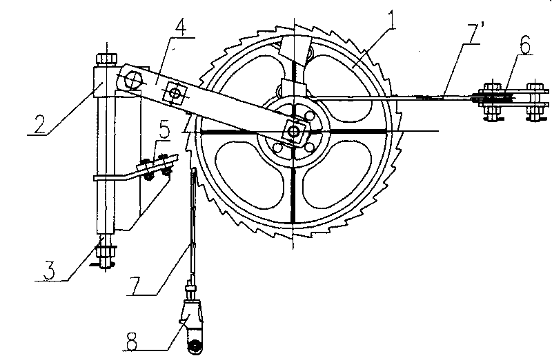
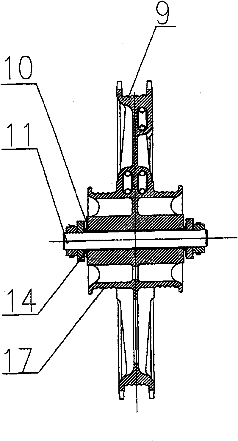
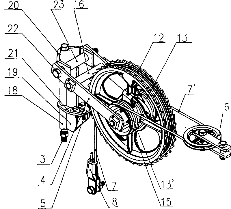
[0022] combined with figure 1 , 2 , 3, 4, 5 describe an embodiment of the present invention.

[0023] A new type of ratchet compensation device, including ratchet body 1, ratchet brake frame 2, long bolt pin 3, ratchet frame connecting lever 4, brake clamp plate 5, balance wheel 6, steel wire rope I 7 steel wire rope II 7' and double ear wedge Wire clamp 8. The ratchet body 1 is installed on the ratchet shaft 11 through a pair of flanging copper-based self-lubricating sliding bearings 10, and the flanging is located on the outside. The two ends of the ratchet shaft 11 are fixed on the front end of the ratchet frame connecting plate 4, and the two ends of the ratchet shaft 11 are equipped with end face self-lubricating bearings 14, and the end face self-lubricating bearings 14 are located between the ratchet frame connecting plate 4 and the self-lubricating sliding bearing 10 , when the ratchet body deviates so that the flanging of the self-lubricating sliding bearing is in ...


PUM


Abstract

The invention provides a novel ratchet compensating device. The novel ratchet compensating device comprises a ratchet body (1), a ratchet brake bracket (2), a long bolt pin (3), a ratchet frame connecting plate (4), a brake pallet (5), a balancing wheel (6), a wire cable I (7), a wire cable II (7') and a wire clamp (8), wherein the ratchet body (1) is arranged on a ratchet shaft (11) through a pair of self-lubricating sliding bearings (10); the two ends of the ratchet shaft (11) are fixed to the front end of the ratchet frame connecting plate (4), and are provided with end face self-lubricating bearings (14); and the end face self-lubricating bearings (14) are arranged between the ratchet frame connecting plate (4) and the self-lubricating sliding bearings (10). By optimizing the structural design, the manufacturing technique is simplified, the safe use performance is improved, the use working tension reaches 32kN, and a compensation distance reaches 950m. The novel ratchet compensating device not only can meet the requirements of high tension and compensation distance in a contact net of a high-speed electric railway, but also brings convenience to installation and maintenance.

Description

technical field [0001] The invention relates to a novel ratchet compensation device, which belongs to the technical field of high-speed electrified railway catenary component manufacturing. Background technique [0002] The ratchet compensating device is mainly used to compensate and adjust the tension of the cable at the anchorage of the electrified railway catenary and the flexible suspension of urban rail transit. With the development of high-speed electrified railways, the speed of passenger dedicated lines continues to increase, and the tension requirements for catenary are higher (the compensation tension of the line is increased to 30kN), so the comprehensive performance of the ratchet compensation device must meet the requirements of large tension compensation. However, due to the small compensation distance of the existing ratchet compensation device, the rated working tension is small (the maximum compensation tension of the line is 15kN); the compensation rope has...

Claims


Application Information

Patent Timeline
Patent Type & Authority Applications(China)
IPC IPC(8): B60M1/26
CPCB60M1/26
Inventor 余福鼎李增勤龚建刚杨小林王红喜陈永瑞王永义张旭峰赵金凤杜敏李昱王展翔
Owner CHINA RAILWAY HIGH SPEED ELECTRIFICATION EQUIP CORP LTD
Why Eureka
Try Eureka