Novel ratchet compensating device
A compensating device, ratchet technology
- Summary
- Abstract
- Description
- Claims
- Application Information
AI Technical Summary
Problems solved by technology
Method used
Image
Examples
Embodiment Construction
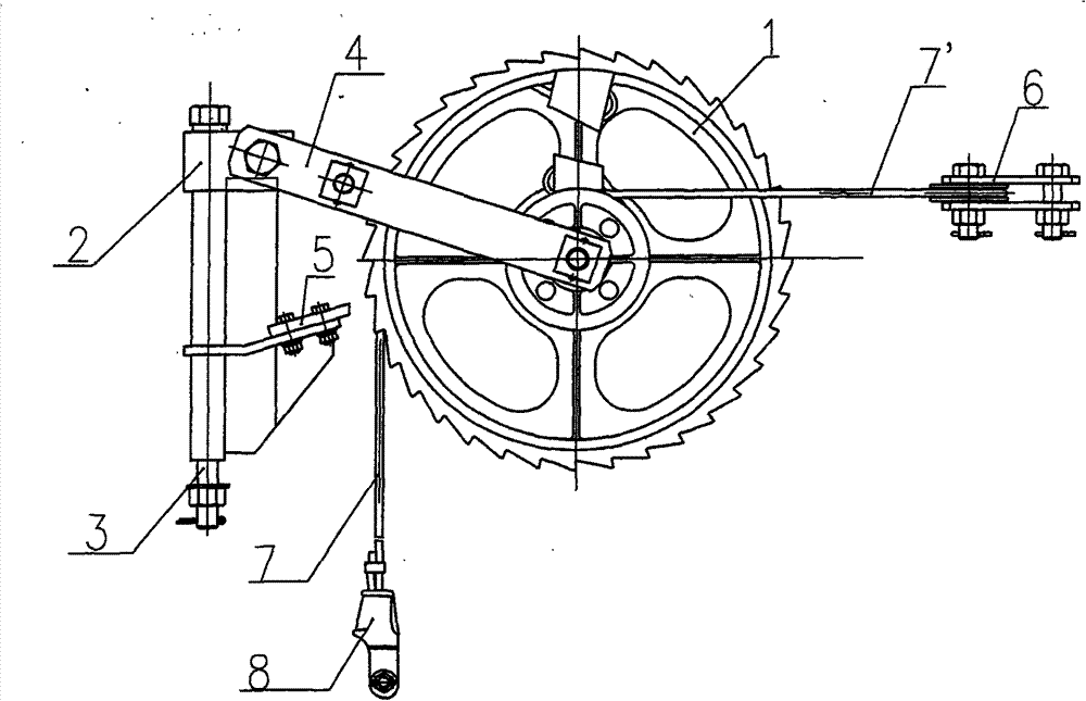
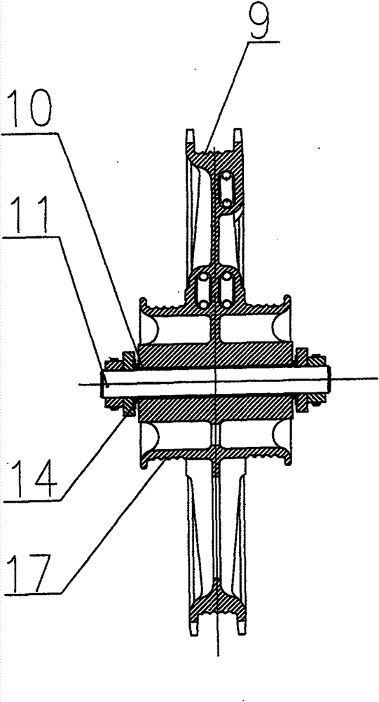
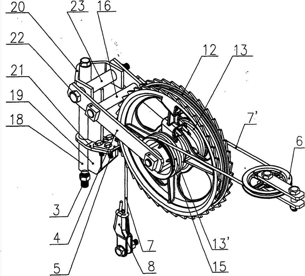
[0022] combined with figure 1 , 2 , 3, 4, 5 describe an embodiment of the present invention.
[0023] A ratchet compensating device, comprising a ratchet body 1, a ratchet brake frame 2, a long bolt pin 3, a ratchet frame connecting lever 4, a brake clamp 5, a balance wheel 6, a steel wire rope I 7, a steel wire rope II 7' and double ear wedges Wire clamp 8. The ratchet body 1 is installed on the ratchet shaft 11 through a pair of flanging copper-based self-lubricating sliding bearings 10, and the flanging is located on the outside. The two ends of the ratchet shaft 11 are fixed on the front end of the ratchet frame connecting plate 4, and the two ends of the ratchet shaft 11 are equipped with end face self-lubricating bearings 14, and the end face self-lubricating bearings 14 are located between the ratchet frame connecting plate 4 and the self-lubricating sliding bearing 10 , when the ratchet body deviates so that the flanging of the self-lubricating sliding bearing is in...
PUM
 Abstract
Description
Claims
Application Information
 - R&D
- Intellectual Property
- Life Sciences
- Materials
- Tech Scout
- Unparalleled Data Quality
- Higher Quality Content
- 60% Fewer Hallucinations
Browse by: Latest US Patents, China's latest patents, Technical Efficacy Thesaurus, Application Domain, Technology Topic, Popular Technical Reports.
© 2025 PatSnap. All rights reserved.Legal|Privacy policy|Modern Slavery Act Transparency Statement|Sitemap|About US| Contact US: help@patsnap.com


