Manually sliding adjusting device of chair

A technology of sliding adjustment and adjustment device, which is applied in the direction of movable seats, etc., can solve the problems of affecting the appearance, danger to users, detachment, etc., and achieve the effect of beautiful appearance.

Inactive Publication Date: 2010-06-09
HSIN CHONG MACHINERY WORKS
View PDF0 Cites 2 Cited by
  • Summary
  • Abstract
  • Description
  • Claims
  • Application Information

AI Technical Summary

Problems solved by technology

[0003] see Image 6 Shown is the slide rail structure used for the existing vehicle seat. It can be clearly seen from the figure that the existing slide rail structure uses the slide bar B to slide in the slide frame A, and one side of the slide frame A There is a slot A1, and the slot A1 is fixed with a clutch control lever A2, and a pull rod A3 that allows the user to control the rotation of the clutch control lever A2 is connected to the clutch control lever A2, so that the user can control the clutch control lever The locking part A21 of A2 releases or locks on the protruding tooth B1 of the slide bar B, so that the slide bar B can slide or be positioned on the slide frame A at will. It is installed on the side of the sliding frame A, so the sliding frame A can only be provided with the protruding tooth B1 on one side, and when the vehicle collides, the locking part A21 of the clutch control lever A2 is easy to break away from the protruding tooth due to excessive momentum B1, and then let the seat slide forward quickly, causing danger to the user, and because the clutch control lever A2 will not move with the slide bar B, the pull rod A3 must be extended for a longer distance to prevent the user from moving the seat When adjusting forward, the pull rod A3 is covered too much so that the user cannot easily pull the pull rod A3. If the user adjusts the seat backward, the pull rod A3 exposes too much of the seat and affects the appearance

Method used


Image

  • Manually sliding adjusting device of chair
  • Manually sliding adjusting device of chair
  • Manually sliding adjusting device of chair

Examples


Embodiment Construction

[0015] The above and other technical features and advantages of the present invention will be described in more detail below in conjunction with the accompanying drawings.

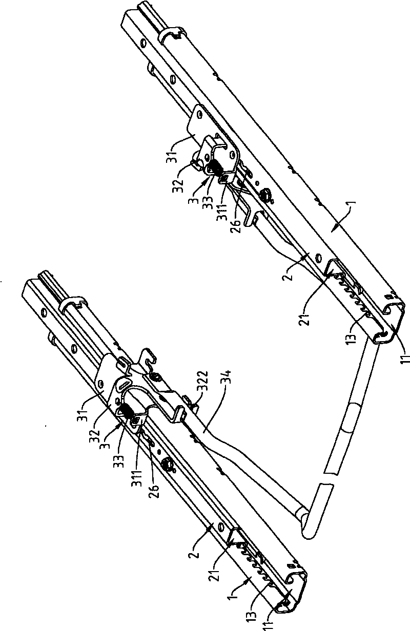
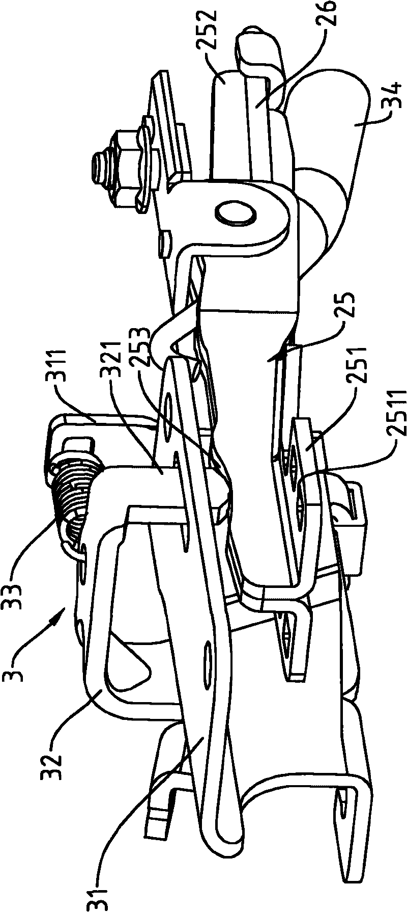
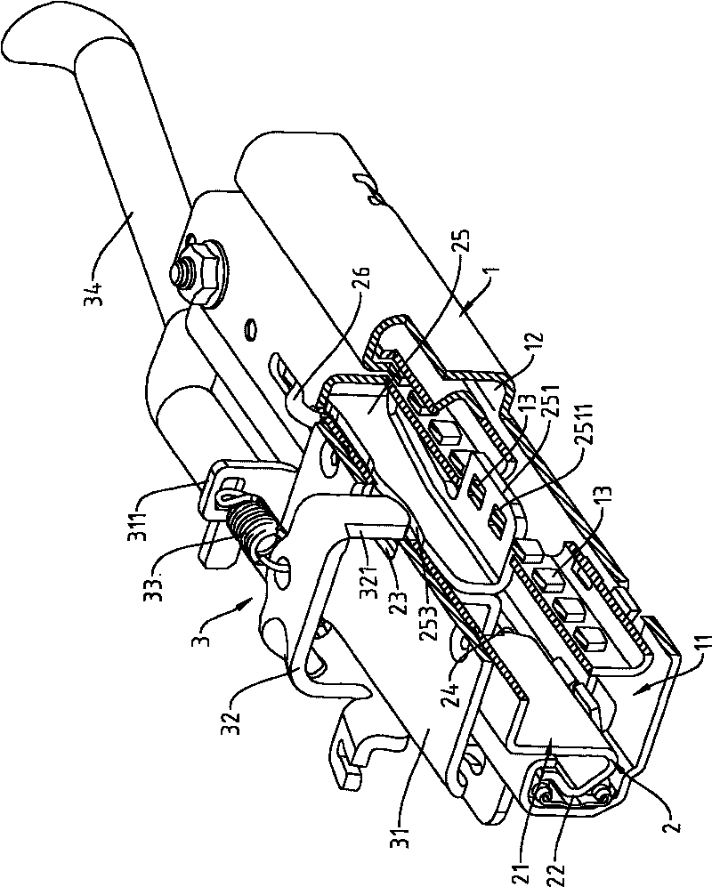
[0016] see Figure 1 to Figure 3 As shown, it can be clearly seen from the figure that the adjustment device of the present invention is relatively arranged on the two sides of the bottom surface of the preset seat (not shown in the figure), and the adjustment device is fixed with a base 1, and a movable seat is arranged above the base. A sliding seat 2 for fixing the preset seat and sliding in the base 1, and a pressing device 3 is arranged on the sliding seat 2, wherein:

[0017] The base 1 has a first accommodating space 11, and the two sides of the first accommodating space 11 are respectively provided with positioning spaces 12, and above the two sides of the first accommodating space 11, a plurality of positioning columns are arranged downwards. 13.

[0018] The sliding seat 2 is located in the fir...


PUM


Abstract

This invention is a manually sliding adjusting device of a chair, which is relatively arranged at the two sides of the preset chair bottom surface, while a base is fixedly arranged on the adjusting device, and a sliding base which can fix the preset chair and slide above the base; a pressing device is arranged on the sliding base; the base is provided a first holding space; a plurality of locating posts is arranged at the two sides of the first holding space; a clamping master unit located on the locating post is arranged in the sliding base provided with a locating piece; a pressing piece is arranged on the locating piece in a pivot manner, while a pressing piece can press on the pressing part to lead the clamping master unit to move up and down; and one side of the pressing piece is connected with a pull rod which enables users to rotate the pressing piece, thus the bearing capacity of the clamping muster unit can be improved effectively so as to prevent the clamping must unit from separating from the locating post or breaking. Because the clamping muster unit moves with the sliding base, the pull rod connected by the clamping muster unit also moves, for avoiding the hard use of the pull rod while the position of the chair changes.

Description

technical field [0001] The invention relates to an adjustment device used for adjusting the front and rear positions of a vehicle seat, in particular to a manual sliding adjustment device for a seat. Background technique [0002] Generally, seats used in automobiles are assembled by a slide rail structure in which a slide frame and a slide bar cooperate with each other to provide the seat with front and rear sliding functions. [0003] see Image 6 Shown is the slide rail structure used for the existing vehicle seat. It can be clearly seen from the figure that the existing slide rail structure uses the slide bar B to slide in the slide frame A, and one side of the slide frame A There is a slot A1, and the slot A1 is fixed with a clutch control lever A2, and a pull rod A3 that allows the user to control the rotation of the clutch control lever A2 is connected to the clutch control lever A2, so that the user can control the clutch control lever The locking part A21 of A2 rele...

Claims


Application Information

Patent Timeline
Patent Type & Authority Applications(China)
IPC IPC(8): B60N2/07
Inventor 江贵交
Owner HSIN CHONG MACHINERY WORKS
Why Eureka
Try Eureka