Extruder waste heat recycling device based on energy-saving technology

A technology of extruder and thermal cycle, which is applied in the field of extruder waste heat recycling device based on energy-saving technology, can solve the problems of difficult heat utilization and poor heat utilization rate, and achieve the effect of avoiding heat dissipation

Inactive Publication Date: 2020-09-11
邓京
View PDF5 Cites 2 Cited by
  • Summary
  • Abstract
  • Description
  • Claims
  • Application Information

AI Technical Summary

Problems solved by technology

[0003] The waste heat recycling device in the prior art has a simple structure, and it is difficult to utilize the heat generated by gear friction when the extruder is working, and in the process of

Method used


Image

  • Extruder waste heat recycling device based on energy-saving technology
  • Extruder waste heat recycling device based on energy-saving technology
  • Extruder waste heat recycling device based on energy-saving technology

Examples


Embodiment 1

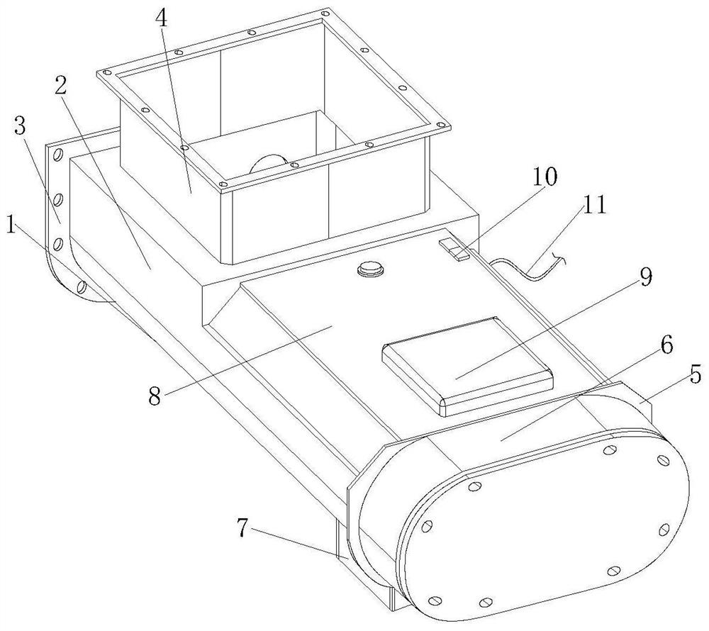
[0030] see figure 1 , an extruder waste heat recycling device based on energy-saving technology of the present invention, the heat cycle main body 1 includes a frame seat 2, a connecting flange piece 3, a feeding frame 4, a connecting piece 5, a transmission mechanism 6, and a discharging frame 7 , a processing chamber 8, a top cover 9, a control switch 10 and a power cord 11, the left end of the frame base 2 is welded and fixed with a connecting flange piece 3, the top left side of the frame base 2 is integrally formed with a feed frame 4, and the frame base 2. The right end surface is fixed with the transmission mechanism 6 through the connecting piece 5. The discharge frame 7 is integrally formed on the right side of the bottom of the frame base 2. The right side of the frame base 2 is embedded with a processing chamber 8, and the right side of the top of the processing chamber 8 is plugged in. A top cover 9 is fixed, a control switch 10 is provided on the top left side of ...

Embodiment 2

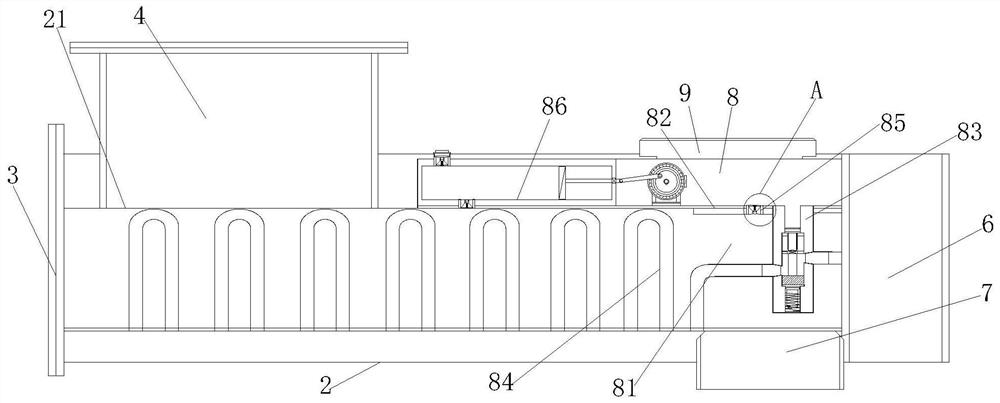
[0037] In an extruder waste heat recycling device based on energy-saving technology of the present invention, a feeding tube 21 is embedded in the middle side of the frame seat 2, and the left side of the top of the feeding tube 21 is connected with the feeding frame 4, and the feeding tube 21 The right side of the bottom is connected with the discharge frame 7, and the extruding work is carried out inside the feeding tube 21. When the bolt rod 839 is located on the top side inside the barrel seat 831, the right side of the clamping block 836 fits inside the inlet pipe 833, so that The inlet pipe 833 is closed to block the internal passage. The valve body 85, the lower valve seat 867 and the upper valve seat 868 have the same structure. The flow direction of the gas inside the valve body 85 is from outside to inside, and the flow direction of the gas inside the lower valve seat 867 is From bottom to top, the flow direction of gas inside the upper valve seat 868 is from bottom t...


PUM


Abstract

The invention discloses an extruder waste heat recycling device based on an energy-saving technology. The extruder waste heat recycling device based on the energy-saving technology comprises a frame seat, a connection flange sheet, a feeding frame, a connection sheet, a transmission mechanism, a discharging frame, a processing cavity, a top cover, a control switch and a power line. According to the extruder waste heat recycling device based on the energy-saving technology, by means of optimal arrangement of the transmission mechanism and the processing cavity, a first gear and a second gear inthe transmission mechanism generate heat during rotation, the heat is transmitted to the surface of a material conveying cylinder through U-shaped pipes, and then the heat is repeatedly utilized; andmeanwhile, a drive motor can be started, under cooperation of a connection rod and a push rod, air in a cavity seat is discharged to the outside, a vacuum environment is formed in the cavity seat, sothat heat dissipation is avoided, heat loss is reduced, and the utilization rate of the heat is increased.

Description

technical field [0001] The invention relates to the related field of extruder waste heat utilization, in particular to an extruder waste heat recycling device based on energy-saving technology. Background technique [0002] According to the flow direction of the head and the angle between the center line of the screw, the extruder can divide the head into a right-angle head and an oblique head, etc.; the screw extruder relies on the pressure and shear force generated by the rotation of the screw, which can make The material can be fully plasticized and evenly mixed, and formed through the die; the material extruder can be basically classified into twin-screw extruder, single-screw extruder and rare multi-screw extruder and screwless extruder ; Current extruders are usually equipped with waste heat recycling devices on the extruders to recycle the heat for economical and environmental protection. [0003] The waste heat recycling device in the prior art has a simple structur...

Claims


Application Information

Patent Timeline
IPC IPC(8): B29C48/275
CPCB29C48/276Y02P70/10
Inventor 邓京
Owner 邓京
Why Eureka
Try Eureka