Check patentability & draft patents in minutes with Patsnap Eureka AI!

Bridge expansion joint device with ability of vertical deflection

A technology of expansion joints and bridges, which is applied in the field of bridge expansion joints, can solve problems such as inappropriateness and complex implementation structures, and achieve the effect of simple structure and low cost

Inactive Publication Date: 2010-06-09
徐斌
View PDF2 Cites 9 Cited by
  • Summary
  • Abstract
  • Description
  • Claims
  • Application Information

AI Technical Summary

Problems solved by technology

[0003] In this solution, the bottom of the movable comb plate needs to be equipped with a rotating shaft that is consistent with the width of the movable comb plate, and several axle seats need to be fixed on the surface of the beam body. The top and bottom must have a certain thickness, and after installation, the surface of the movable comb board needs to be flush with the road surface. In the environment where the bridge deck pavement layer on the surface of the beam body is thin, the shaft seat at the bottom of the movable comb board cannot meet the requirements. thickness, therefore, the implementation of this solution is not very suitable in this environment
Moreover, the implementation structure of this solution is more complicated, and the installation matching is also more particular

Method used


Image

  • Bridge expansion joint device with ability of vertical deflection
  • Bridge expansion joint device with ability of vertical deflection
  • Bridge expansion joint device with ability of vertical deflection

Examples


Embodiment 1

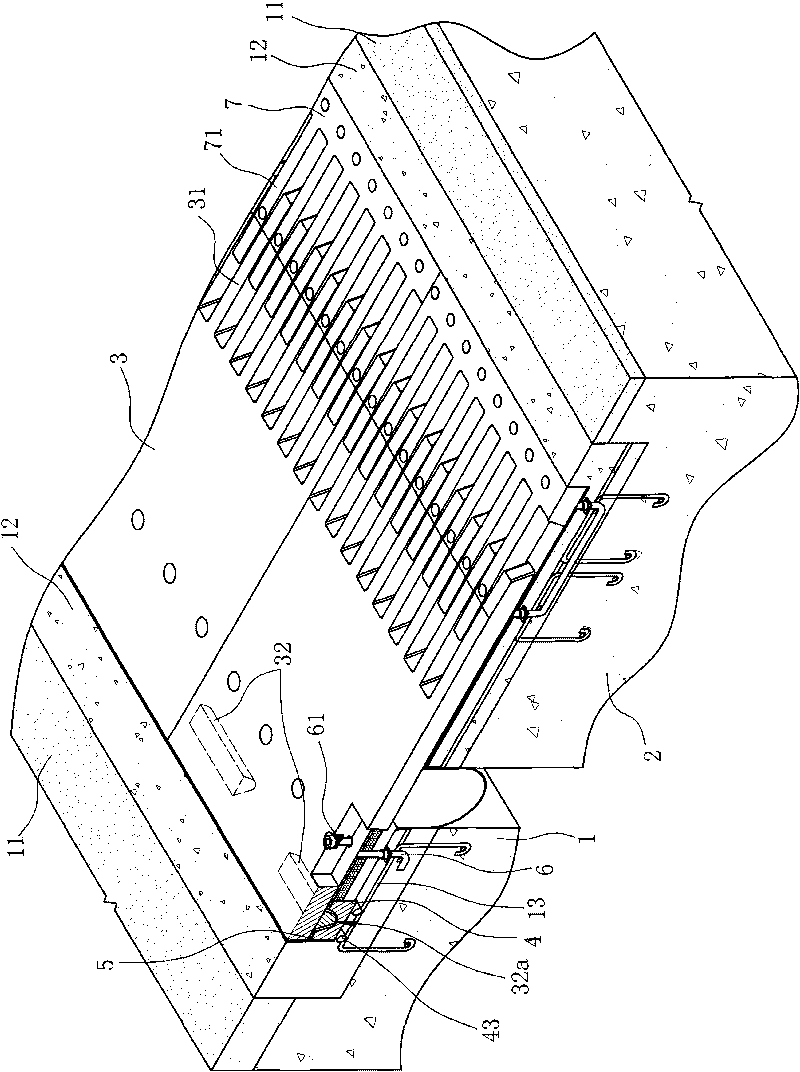
[0026] Such as Figure 1 ~ Figure 3 As shown, the bridge expansion joint device with vertical displacement capability includes a first beam body 1 and a second beam body 2, a movable comb plate 3 arranged on the first beam body 1 and The fixed comb plate 7 arranged on the second beam body 1;

[0027] Wherein, the second end of the movable comb plate 3 is fixed relative to the first beam 1 on one side of the bridge expansion joint, and the first end of the movable comb plate 3 is located on the other side of the bridge expansion joint across the bridge expansion joint. The movable comb plate 3 is a cross seam plate. The first end of the movable comb plate 3 is provided with comb teeth 31 and interacts with the combs of the fixed comb plate 7. The teeth 71 are intersected and arranged at intervals, and a concrete layer 12 is poured between the ends of the movable comb plate 3 and the fixed comb plate 7 and the road surface 11 on the corresponding beam;

[0028] Two supporting legs 3...

Embodiment 2

[0034] Such as Figure 4 As shown, the difference between the second embodiment of the present invention and the first embodiment is that each support seat 4 is fixed relative to the first beam 1 by a U-shaped anchor bar 44 provided at the bottom of the support seat 4.

Embodiment 3

[0036] Such as Figure 5 ~ Figure 8 As shown, the difference between the third embodiment of the present invention and the first embodiment is that the supporting leg 32 is in the shape of an inverted cone, and its end surface 32a is a curved surface, see Figure 5 Shown by the dotted line;

[0037] The supporting base 4 has a square shape with an inverted cone-shaped recess 45 in the center of the surface.


PUM


Abstract

The invention discloses a bridge expansion joint device with the ability of vertical deflection, comprising a transverse joint plate (3) over the bridge expansion joint. At least one downwardly-protruding support arm (32) is arranged at the bottom of the second end of the transverse joint plate (3); the tail end surface (32a) of each support arm (32) is an arc surface corresponding to each support arm (32); corresponding holders (4) are fixed on the bridge body; each holder (4) is provided with a pit (41) the bottom of which is matched with the tail end surface (32a) of the support arm (32); the pit (41) is slightly larger than the corresponding support arm (32); and the tail end of each support arm (32) is supported in the corresponding pit (41). Compared with the prior art, the invention ensures that the support arm at the bottom of the transverse joint plate can rotate freely in the pit of the holder along the second end of the transverse joint plate relative to the rotating direction of the bridge body during vertical corner deflection of the bridge body so that the surface of the transverse joint plate maintains smooth all the time for vehicles to pass successfully; besides, as the holder has a relatively small thickness, therey the invention is particularly suitable for the application environment with a thinner bridge deck pavement layer.

Description

Technical field [0001] The invention relates to the technical field of bridge expansion joints, in particular to a bridge expansion joint device with vertical displacement capability. Background technique [0002] Among the existing bridge expansion joints, the comb type expansion joint with fixed comb plate and movable comb plate is a better one, especially in super large bridge expansion joints with expansion and contraction of more than 300 mm. This is the case for the Chinese invention patent "A super-large flexural comb-type bridge expansion joint device" proposed earlier with the patent number ZL200410049491.5 (publication number CN1333137C). The bridge expansion joint device includes two bridge expansion joints. The fixed comb plate and the movable comb plate on the side beam body, wherein the first end of the movable comb plate is provided with comb teeth and intersected and spaced with the comb teeth of the fixed comb plate, and the bottom of the second end of the movabl...

Claims


Application Information

Patent Timeline
Patent Type & Authority Applications(China)
IPC IPC(8): E01D19/06
Inventor 徐斌
Owner 徐斌
Features
  • R&D
  • Intellectual Property
  • Life Sciences
  • Materials
  • Tech Scout
  • Unparalleled Data Quality
  • Higher Quality Content
  • 60% Fewer Hallucinations
Learn More