Valve for fluid

A fluid and large fluid technology, applied in the field of metal rings, can solve problems such as damage, metal sheets 24 combined into one structure, and corrosion, and achieve the effect of improving service life

Inactive Publication Date: 2010-06-09
SHIE YU MACHINE PARTS IND
View PDF0 Cites 7 Cited by
  • Summary
  • Abstract
  • Description
  • Claims
  • Application Information

AI Technical Summary

Problems solved by technology

[0004] But the common disadvantage of the structure of various conventional fluid valves or valves is: the metal sheet 24 provided by the aforementioned conventional fluid valve upper cover 2 is arc-shaped, and must be composed of multiple pieces, and the metal sheet 24 cannot be connected with the upper cover. Combined into an integrated structure, as mentioned above, the fluid pressure will attack the weaker position of the diaphragm valve, and the joint position of the valve plate 20 and the body 1 is the attacked part, so that the conventional diaphragm valve is damaged because it cannot withstand the fluid pressure. Let the fluid leak out, and the aforementioned metal sheet 24 is exposed to the outside. If the fluid valve is used in acid, alkaline fluid or environment, the metal sheet 24 is vulnerable to acid and alkaline fluid attack and rapid corrosion, reducing the diaphragm valve. Service life and restricted places where it can be used

Method used


Image

  • Valve for fluid
  • Valve for fluid
  • Valve for fluid

Examples


Embodiment Construction

[0030] The fluid valve or valve of the present invention refers to a fluid valve or valve that can be applied to various structures, such as a diaphragm valve; or a diaphragm valve of any type; or a swing diaphragm valve; or a check valve; or a butterfly valve, for To enable your examiner to fully understand the present invention, it is explained as follows according to the attached drawings:

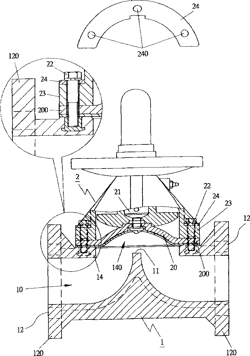
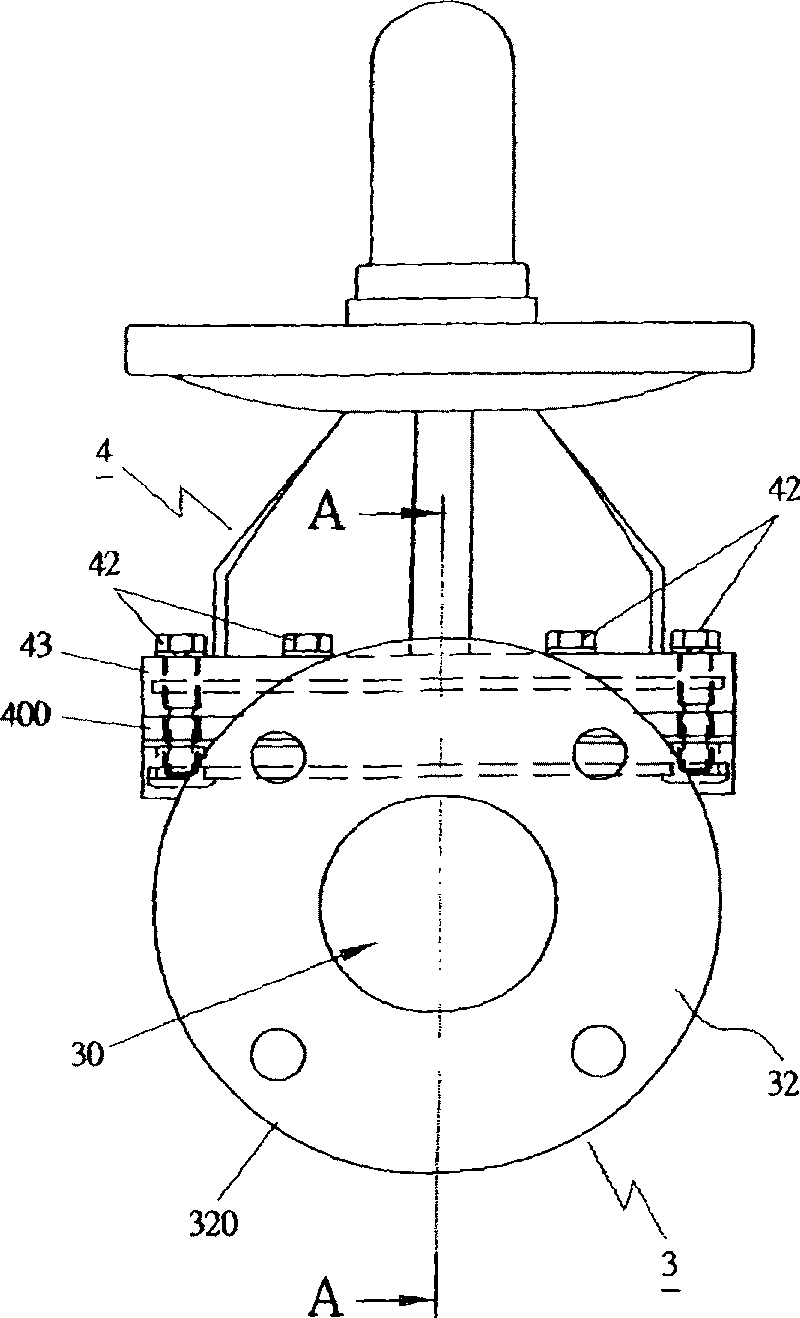
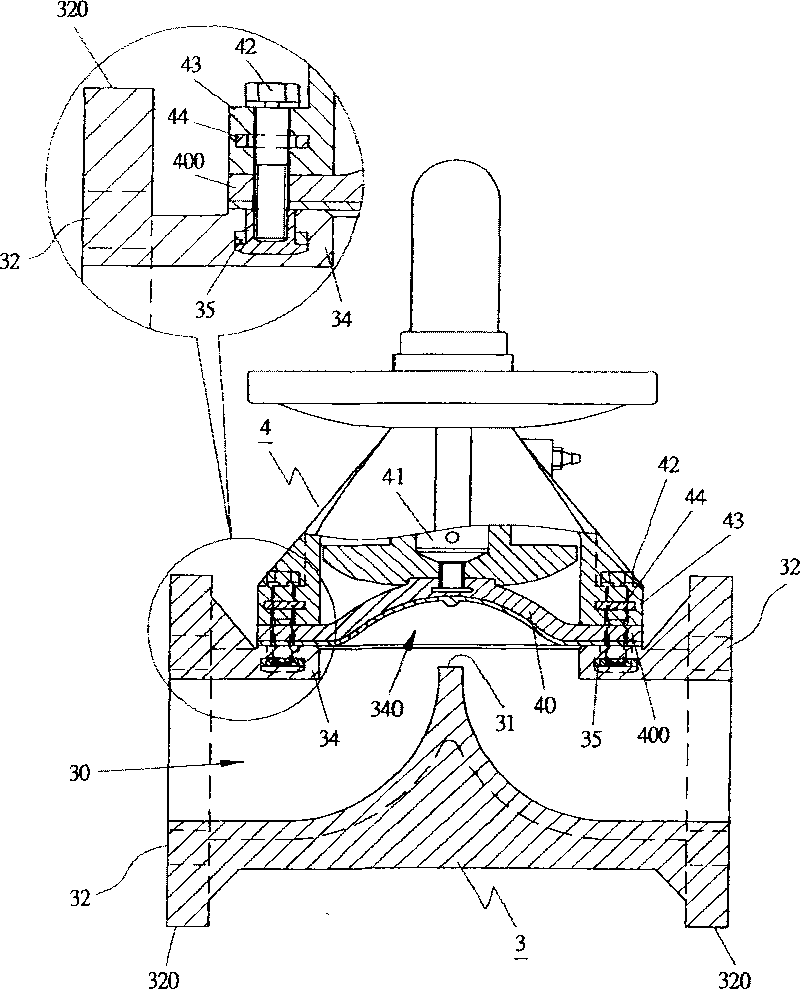
[0031] Such as figure 2 and 3 , Image 6 The embodiments shown are all diaphragm valves; as Figure 7 and 8 The embodiment is by any type (TRUE UNION) diaphragm valve; Figure 9 The embodiment shown is a swing diaphragm valve; as Figure 10 The embodiment shown is a check valve; as Figure 11 and 12 The illustrated embodiment is a butterfly valve, and each of the above embodiments includes:

[0032] The body 3 is provided with an integrally formed fluid flow hole 30 on the body 3, and the flow hole 30 is connected with the image 3 ;or Image 6 ;or Figure 7 ;or Figure 9 T...


PUM


Abstract

The invention relates to a valve for fluid, which is characterized by comprising a body and an upper cover or a joint, wherein a fluid through hole is formed on the body; the body is provided with a combined enclosure; a hole is formed on the inner side of the combined enclosure; the hole and the combined enclosure form a whole to wrap one or more metal rings; and the upper cover or the joint and the combined enclosure form a whole to wrap one or more metal rings. The valve has the advantages that: after the body is combined with the upper cover or the joint, the valve for the fluid can bear higher fluid pressure, the service life of the valve is improved, and the valve is applicable to more places.

Description

technical field [0001] The present invention relates to a valve for fluid, especially a structural innovation of a valve for fluid that can be applied to various structures. The main purpose of the present invention is that one or more metal rings are integrally formed around the combined ring of the body ; and then one or more metal rings are integrally molded around the joint ring of the upper cover or joint, so that when the body is combined with the upper cover or joint, the fluid valve can withstand greater fluid pressure and improve the use of fluid. The service life of the valve can be widely used in various places of use. Background technique [0002] According to commercially available valves for fluids, such as figure 1 As shown, the conventional structure is explained by a diaphragm valve, which includes: a body 1, an integrally formed fluid flow hole 10 is provided inside the body 1, and a flange 11 is located in the center of the fluid flow hole 10, and the Th...

Claims


Application Information

Patent Timeline
Patent Type & Authority Applications(China)
IPC IPC(8): F16K7/16F16K1/226F16K27/00
Inventor 蔡琪隆
Owner SHIE YU MACHINE PARTS IND
Why Eureka
Try Eureka