Lens driving device and urging force adjusting method for elastic member

A technology of lens driving device and elastic parts, which can be used in installation, optical components, instruments, etc., and can solve problems such as increasing the number of parts

Inactive Publication Date: 2010-06-09
MITSUMI ELECTRIC CO LTD
View PDF1 Cites 4 Cited by
  • Summary
  • Abstract
  • Description
  • Claims
  • Application Information

AI Technical Summary

Problems solved by technology

[0006] In the lens driving device disclosed in the aforementioned Patent Document 1, since the lens supporting member is required separately from the lower fixing member (base), there is a problem that the number of parts increases.

Method used


Image

  • Lens driving device and urging force adjusting method for elastic member
  • Lens driving device and urging force adjusting method for elastic member
  • Lens driving device and urging force adjusting method for elastic member

Examples


Embodiment Construction

[0020] Hereinafter, embodiments of the present invention will be described with reference to the drawings.

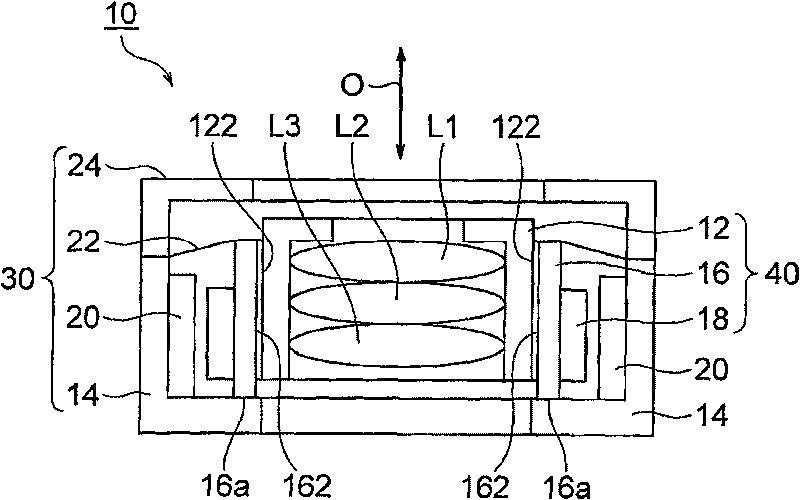
[0021] refer to figure 1 , in order to facilitate the understanding of the present invention, the relevant lens driving device 10 will be described. figure 1 It is a schematic sectional view showing main parts inside the lens driving device 10 . exist figure 1 In the example shown, the up-down direction is the direction of the optical axis O of the lens.

[0022] However, in an actual use situation, the direction of the optical axis O, that is, the up-down direction is the front-rear direction. In other words, the upward direction is the front direction, and the downward direction is the rear direction.

[0023] The illustrated lens driving device 10 is equipped with a mobile phone with an auto-focusable camera. The lens driving device 10 is used to move the lens drum 12 including the plurality of lenses L1, L2, and L3 in the optical axis O direction. The lens dri...


PUM


Abstract

The invention provides a lens driving device for adjusting an urging force for an elastic member without increasing the number of members and an urging force adjusting method for the elastic member. In a lens driving device including a lens barrel having an outer wall in which a male screw thread is cut, a tubular lens holder having an inner wall in which a female screw thread is cut, a driving coil fixed to the lens holder so as to position around the lens holder, a fixed portion including a magnetic field generating portion including a permanent magnet opposite to the driving coil, and an elastic member mounted to the lens holder and the fixed portion and supporting the lens holder in a direction of an optical axis shiftably so as to position the lens holder in a radial direction, the lens barrel has a lower end portion which makes contact with a base of the fixed portion in a state where the driving coil is not energized.

Description

technical field [0001] The present invention relates to a lens driving device, and more particularly to a lens driving device for autofocusing used in a portable compact camera. Background technique [0002] A portable compact camera is mounted on a mobile phone with a camera. A lens driving device for autofocus is used in this portable compact camera. Conventionally, various autofocus lens drive devices have been proposed. [0003] Such an autofocus lens driving device includes a cylindrical lens holder holding a lens barrel including a lens, and a driving coil is fixed around the lens holder. A magnetic field generator including a magnet is arranged to face the driving coil. The magnetic field generating part is fixed on the base. A combination of a lens barrel (lens barrel), a lens holder (lens holder), and a driving coil functions as a movable part of a lens driving device. On the other hand, the combination of the magnetic field generating unit and the base functio...

Claims


Application Information

Patent Timeline
Patent Type & Authority Applications(China)
IPC IPC(8): G02B7/02G02B7/08G02B7/04
CPCG02B7/08G02B7/021
Inventor 三浦伸之
Owner MITSUMI ELECTRIC CO LTD
Why Eureka
Try Eureka