
Tensioner

A technology of tensioning device and plunger, which is applied in the direction of transmission device, belt/chain/gear, mechanical equipment, etc., can solve the problems that the tensioning device cannot ensure oil, the number of parts is large, and the structure is complicated, and the structure is simple, The number of parts is simple and the effect of maintaining the lubrication effect

Active Publication Date: 2016-05-11
TSUBAKIMOTO CHAIN CO
View PDF9 Cites 0 Cited by
  • Summary
  • Abstract
  • Description
  • Claims
  • Application Information

AI Technical Summary

Problems solved by technology

[0014] Furthermore, if a high degree of sealing is not performed between the wall surface and the main body of the tensioner, the oil in the reservoir (oil storage chamber R) may flow out during a long-term stop.
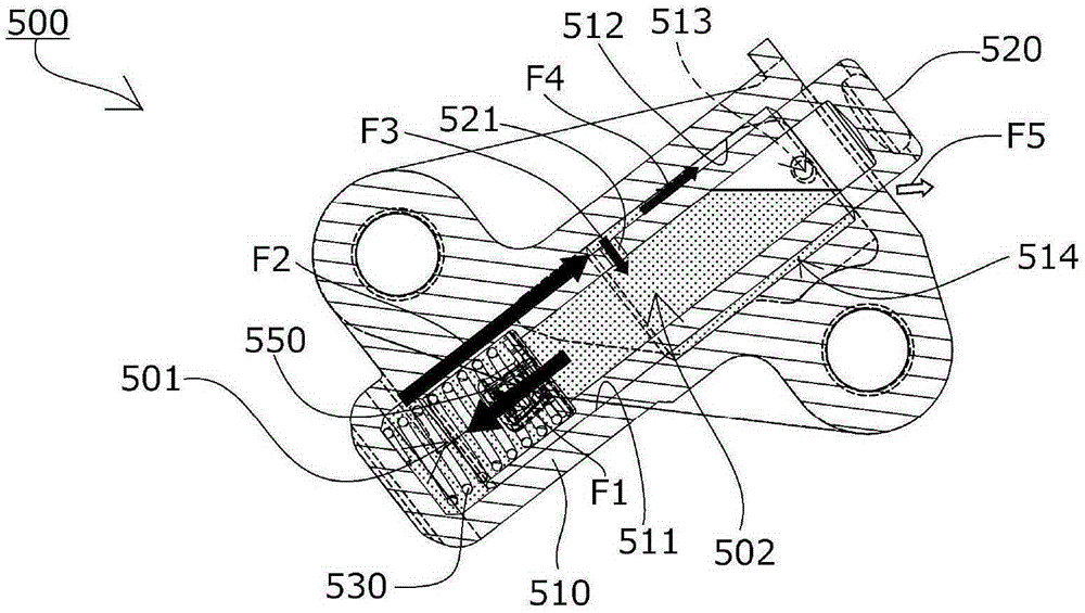
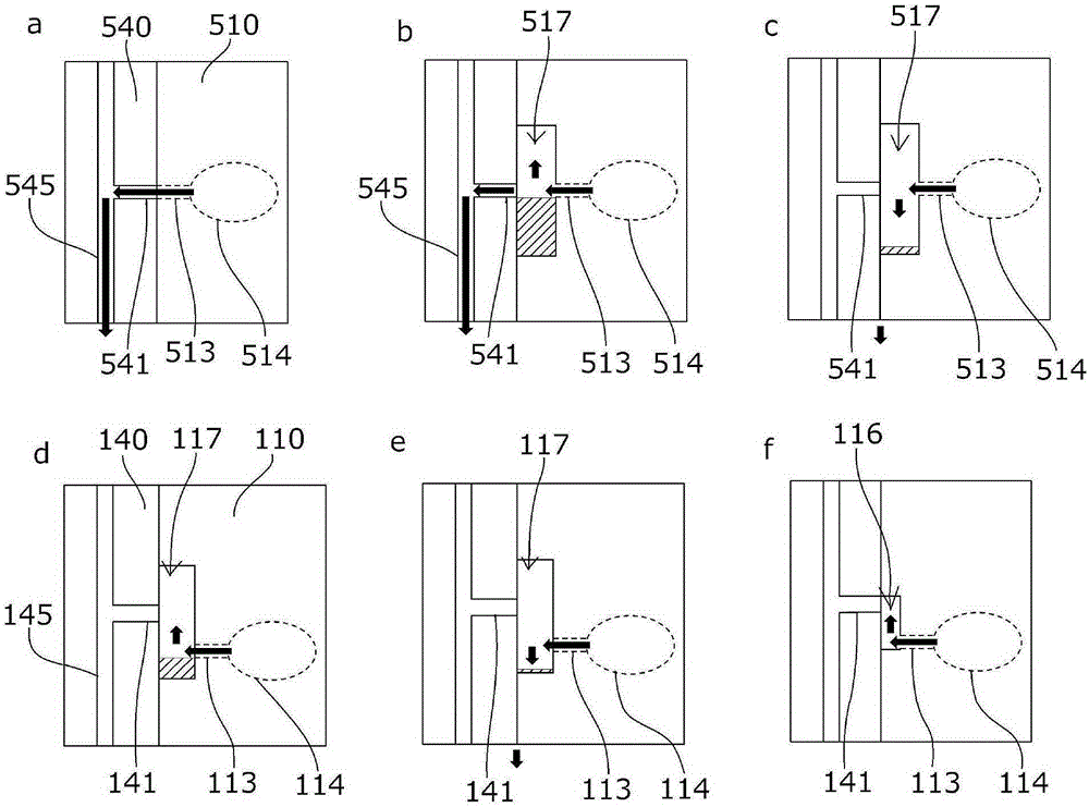
[0015] In the tensioning devices shown in Patent Document 2 and Patent Document 3, although the oil flowing out from the gap between the plunger receiving hole 111 and the plunger 120 due to the reciprocating motion of the plunger during restarting is reduced, the oil flow in the plunger is promoted at the same time. The housing hole 111 and the plunger 120 circulate internally, but since part of the circulating oil flows out from the main body supply hole (oil supply hole 114 ) to the outside of the plunger housing hole 111, there is a large time lag until the supply of high-pressure oil is started. , it is possible that sufficient oil cannot be ensured in the tensioner
[0016] In addition, the tensioning devices shown in Patent Document 2 and Patent Document 3 are as follows. Since a large amount of oil is accumulated in the plunger receiving hole 111 and the plunger 120 to promote the internal circulation of the oil, the number of parts is large and the structure is changed. complicated

Method used


Image

  • Tensioner
  • Tensioner
  • Tensioner

Examples


Embodiment

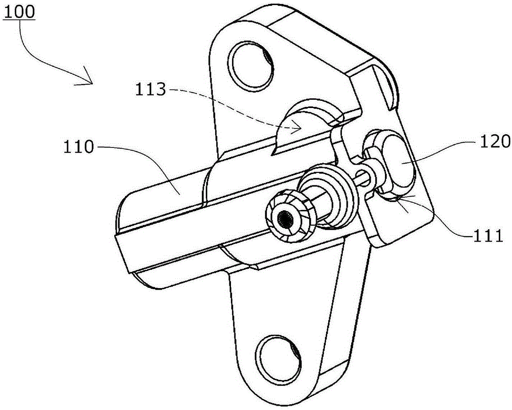
[0059] Such as image 3 , Figure 4 As shown, the tensioner 100 according to one embodiment of the present invention includes: a tensioner body 110 having a cylindrical plunger receiving hole 111 with one side open; a cylindrical plunger 120 slidably inserted into the In the plunger receiving hole 111; and the urging unit, that is, a coil spring, is freely accommodated in the pressure oil chamber formed between the plunger receiving hole 111 and the rear end side of the plunger 120, and faces the plunger in the protruding direction. apply force.

[0060] The inside of the tensioner main body 110 and the structure of the plunger 120 are the same as those of the aforementioned tensioner 500 except for the position of the main body supply hole 113 .

[0061] The main body supply hole 113 is provided more upward than the region where the plunger receiving hole 111 is projected on the wall surface in the horizontal direction, and is provided so as to communicate with an internal ...


PUM


Abstract

To provide a tensioner which can circulate a sufficient amount of oil even if there is a long time lag until pressurized oil starts to be supplied, and which exhibits a lower level of leak of oil stored therein, and which is structured simply without increasing the number of components therefore. The tensioner includes: a tensioner body having a plunger bore; a cylindrical plunger slidably inserted into the plunger bore; and biasing means for urging the plunger outward. When the tensioner is fixed to a wall surface, a body hole that extends from the wall surface up to a circumferential surface of the plunger bore is located lower than an oil discharge hole in the wall surface.

Description

technical field [0001] The present invention relates to a tensioning device, which is fixed on a wall surface having an oil discharge hole, and comprises: a tensioning device main body having a plunger receiving hole opened on one side; a cylindrical plunger slidably inserted into a column a plug receiving hole; and a force applying unit that applies force to the plunger in a protruding direction. Background technique [0002] Conventionally, in the transmission device used in the timing system of the engine, etc., the tension device that applies appropriate tension to the slack side of the transmission belt or the transmission chain and is used to suppress the vibration generated during the movement has been widely used, and the following tension device is known. It has: a main body of the tensioning device, which has a plunger receiving hole opened on one side; a cylindrical plunger, which is inserted into the plunger receiving hole freely and slidably; The tightening dev...

Claims


Application Information

Patent Timeline
Patent Type & Authority Applications(China)
IPC IPC(8): F16H7/08
CPCF16H7/08F16H2007/0812
Inventor 吉田修前田宗裕榑松勇二
Owner TSUBAKIMOTO CHAIN CO
Learn More