
Porous mask plate capable of being recognized by APS solar sensor

A solar sensor and mask technology, which is applied in the fields of instruments, optics, and photoengraving process of pattern surface, can solve the problems of unsuitable engineering application and complicated identification process, and achieves improvement of measurement accuracy, reduction of hardware resources, The effect of improving the data update rate

Active Publication Date: 2010-06-09
BEIJING INST OF CONTROL ENG
View PDF2 Cites 3 Cited by
  • Summary
  • Abstract
  • Description
  • Claims
  • Application Information

AI Technical Summary

Problems solved by technology

The mask plate of the APS solar sensor based on MEMS technology described in the literature is an equidistant porous array. When the imaging holes are polluted, the identification process is complicated, and it is also not suitable for engineering applications.
[0007] "Optical Technology" Volume 32 No. 2, March 2006, "Optical System Design of Small Hole Array Solar Sensor" The identifiable mask imaging holes involved in the article are also equally spaced porous arrays, which are only theoretical The above research results, when the imaging hole is polluted, the recognition process is complicated, and it is also not suitable for engineering applications

Method used


Image

  • Porous mask plate capable of being recognized by APS solar sensor
  • Porous mask plate capable of being recognized by APS solar sensor
  • Porous mask plate capable of being recognized by APS solar sensor

Examples


Embodiment 1

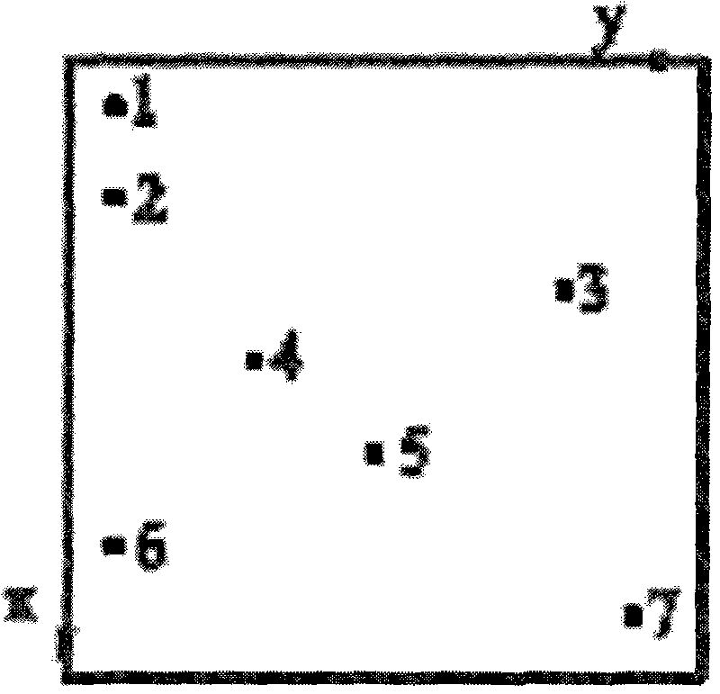
[0025] The invention solves the problem of identifying when the imaging holes in the imaging hole array of the porous mask plate are blocked by the APS imaging sun sensor due to the lunar dust environment during the landing and running stages of the lunar probe. In the moon dust environment, the sensor can be quickly and accurately identified when it is polluted by moon dust, and the polluted points can be eliminated through subsequent algorithms, so as to maintain high precision and high reliability when the sensor is polluted by moon dust. Specifically divided into three aspects:

[0026] a. Determination of the imaging hole array scheme of the identifiable porous mask

[0027] b. Determination of the optimal pore size of the identifiable porous mask

[0028] c. Chromium coating with low reflectivity in laminated structure

[0029] The manufacturing process of the identifiable porous mask plate of the present invention will be described in detail below according to specifi...

Embodiment 2

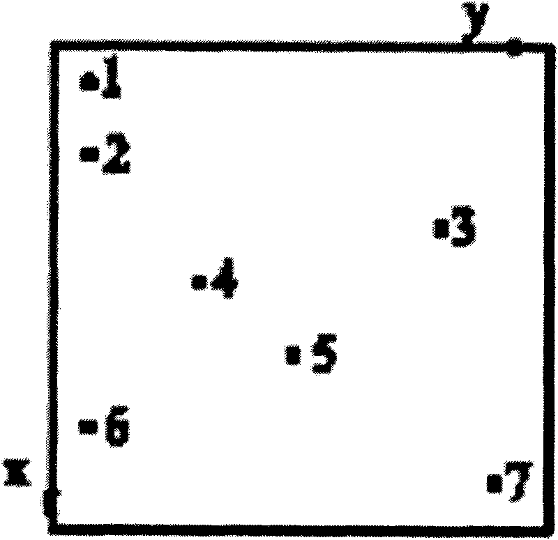
[0047] When the number of small holes is 5, the distance between any two small holes in the x direction and the distance in the y direction is 30 pixels, and the side length of the square area of ​​the imaging small hole is 4.05 mm. The positional relationship between each small hole is shown in Table 2:

[0048] Table 2 Positional relationship between imaging pinholes

[0049] (x,y)

[0050] The plate-making process is the same as that in Example 1, and the mask plate is installed on the image sensor and assembled into a machine for testing. It is also measured that the measurement accuracy obtained by the APS sun sensor meets the requirements.


PUM

PropertyMeasurementUnit
Transmittanceaaaaaaaaaa

Abstract

The invention relates to a porous mask plate capable of being recognized by an APS solar sensor, which comprises a glass substrate and a film coating layer, wherein a film is coated on the lower surface of the glass substrate; at least 3 imaging pinholes are optically etched on the film coating surface of the glass substrate; the difference of the distance in at least one of the x direction and the y direction between any two imaging pinholes is not less than 20 pixels; and the side length of the square zone boundary of the imaging pinholes does not exceed d=L-2htan alpha (unit: mm), wherein L is the side length of the effective image plane of an image sensor in the APS solar sensor, h is the distance between the mask plate and the image plane of the image sensor, and alpha is the angle of field of the APS solar sensor. By adopting independent characteristics between holes in the porous array, the invention can quickly recognize contaminated pinholes, ensures high data updating rate of products, and is suitable for engineering application.

Description

technical field [0001] The invention belongs to the field of optical imaging attitude sensors, and is especially suitable for identifiable porous mask plates of solar sensors. Background technique [0002] With the rapid advancement of imaging detection devices and processor technology, solar sensors for spacecraft are gradually developing from encoded and analog to imaging. APS solar sensors are a large field of view that is different from traditional encoded solar sensors. , High-precision imaging sun sensor. [0003] The identifiable porous mask is an APS imaging sun sensor light introducer, and its main function is to image the sun on the surface of the photosensitive device. During the landing phase of the lunar rover and the movement of the lunar surface, moon dust poses a great threat to the normal operation of the optical sensor. The identifiable porous mask will mask the The diaphragm is divided into several specific areas, so that the APS imaging solar sensor can...

Claims


Application Information

Patent Timeline
IPC IPC(8): G03F1/14G01C21/02G03F1/48
Inventor 崔坚张建福余成武莫亚男王立刘江
Owner BEIJING INST OF CONTROL ENG
Learn More