Light shield layer structure with infrared ray hole of flat plate display

A flat-panel display and infrared technology, which is applied to the structure of telephones, instruments, identification devices, etc., can solve problems such as differences in reflectivity, increased production costs, and imperishable colors, so as to maintain consistency, simplify processes, and reduce costs. The effect of good appearance and visual effects

Inactive Publication Date: 2010-06-09
湖南普照爱伯乐平板显示器件有限公司
View PDF0 Cites 7 Cited by
  • Summary
  • Abstract
  • Description
  • Claims
  • Application Information

AI Technical Summary

Problems solved by technology

However, due to the different materials used in the light-shielding layer and the IR ink produced by this production method, the reflectivity is different. When using it, the eye's viewing angle direction is the back of the substrate. Under the reflected light, the colors of the light-shielding layer and the IR hole cannot be perfectly consistent. The outline of the visible opening affects the appearance of the product; and the light-shielding layer and IR ink are produced by different production equipment and processes, which increases the production cost

Method used


Image

  • Light shield layer structure with infrared ray hole of flat plate display
  • Light shield layer structure with infrared ray hole of flat plate display
  • Light shield layer structure with infrared ray hole of flat plate display

Examples


Embodiment 1

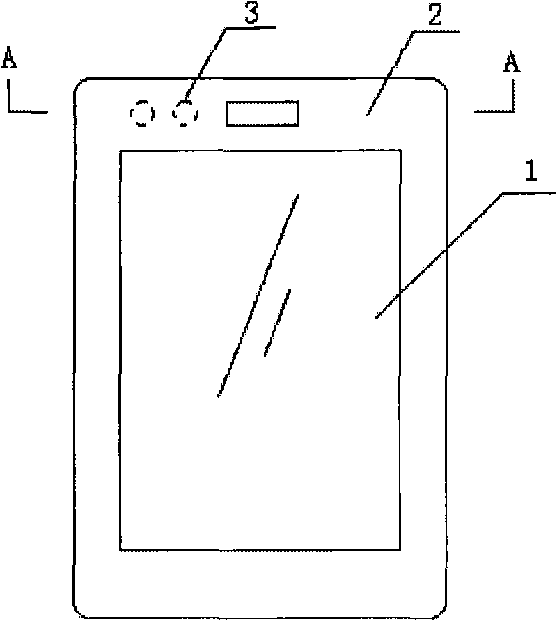
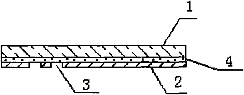
[0012] image 3 Shown is a light-shielding layer structure with an infrared hole for a flat-panel display of a mobile phone touch screen, including a light-transmitting substrate 1 and a light-shielding layer 2 with an infrared hole (IR hole) 3 on the substrate, on the light-transmitting substrate 1 and A layer of infrared light-transmitting material (IR material) 4 is arranged between the light-shielding layers 2 .

[0013] Manufacture process: on the part of the light-transmitting substrate 1 corresponding to the light-shielding layer 2, a layer of infrared light-transmitting material (IR material) 4 is first produced by deposition or coating method, and then the light-shielding material with infrared light-transmitting holes (IR hole) 3 is made Layer 2, so that the reflectivity of the entire light-shielding layer area (including the IR hole) can be consistent, and the IR hole area can realize the infrared transmission function.

[0014] The light-transmitting substrate inc...

Embodiment 2

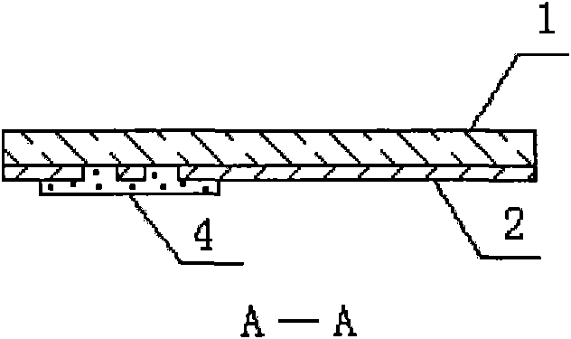
[0016] The present invention also provides another structural mode, that is, the infrared light-transmitting material (IR material) 4 can be made into multiple layers (see Figure 4 ), according to the different color requirements of the light-shielding layer of the flat panel display, the lens (Lens) with different color effects can be produced after superposition of multiple layers of IR materials, and the overall appearance of the mobile phone can be maintained.


PUM


Abstract

The invention discloses a light shield layer structure with an infrared ray hole of a flat plate display. The structure comprises a non-light tight substrate and a light shield layer with an infrared ray through hole on the substrate, wherein at least one layer of infrared non-light tight material is arranged between the non-light tight substrate and the light shield layer. Because the same plane is provided with the same infrared non-light tight material, the light shield layer structure not only can meet the requirement on the permeation of the infrared rays, but also can keep the consistency of reflectance, thereby achieving an excellent appearance visual effect. The infrared ray through hole positioned on the light shield layer behind the infrared non-light tight material cannot be seen from a viewing direction of a lens, so the disadvantage of inconsistent reflectances caused by two different materials existing on the same plane in the prior art is overcome. Simultaneously, the light shield layer structure with the infrared ray hole of the flat plate display can be manufactured by the same production equipment and process in the manufacturing process so as to achieve the purpose of simplifying the process and lowering the cost.

Description

technical field [0001] The invention belongs to optical devices, in particular to a light-shielding layer structure with infrared holes for a flat panel display. Background technique [0002] The shading layer of the flat panel display is mainly used in the field of liquid crystal display, such as the display protective lens (Lens) of the mobile phone, the protective lens (Touch Lens) of the touch screen, etc., and its main function is to protect the parts of the non-display area of ​​the liquid crystal display block. It is characterized by good shading properties, relatively high optical density (above 3.0 in the 550nm band), and is opaque in visible light and near and mid-infrared regions. Now mobile phones and other communication devices have more and more extended functions, such as cameras, bluetooth, infrared transmission, etc., because the light-shielding layer is very good, so it affects the function of infrared transmission. The current general solution is: in the ...

Claims


Application Information

Patent Timeline
IPC IPC(8): G09F9/35H04M1/02
Inventor 韩荣敏林荣丰卞鸣锴
Owner 湖南普照爱伯乐平板显示器件有限公司
Why Eureka
Try Eureka