Method and system for transmission of message in optical communication system and optical line terminal

An optical communication system and optical line terminal technology, applied in the field of optical line terminals, can solve problems such as poor flexibility and limited service configuration capacity, and achieve the effect of strong flexibility

Active Publication Date: 2010-06-09
HUAWEI TECH CO LTD
View PDF0 Cites 14 Cited by
  • Summary
  • Abstract
  • Description
  • Claims
  • Application Information

AI Technical Summary

Problems solved by technology

[0005] 1) GPON technology is not related to MPLS technology. Although it is connected to the network through GPON, after OLT terminates GPON, it needs to map user-side data to MPLS tunnel through Ethernet
[0006] 2) Since the data on the user side must pass through the Ethernet to be mapped with the MPLS tunnel, it is subject to some limitations of the Ethernet itself. The OLT cannot map the user-side data to the MPLS tunnel according to the VLAN, and the unified planning of the VLANs between the operators will limit the capacity of the service configuration, and the flexibility is poor

Method used


Image

  • Method and system for transmission of message in optical communication system and optical line terminal
  • Method and system for transmission of message in optical communication system and optical line terminal
  • Method and system for transmission of message in optical communication system and optical line terminal

Examples


Embodiment 1

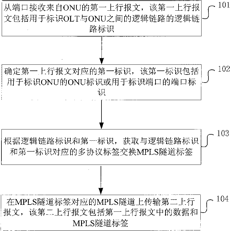
[0045] An embodiment of the present invention provides a method for message transmission in an optical communication system, such as figure 1 As shown, the method includes:

[0046] 101: Receive the first uplink message from the ONU from the port, where the first uplink message includes a logical link identifier for identifying a logical link between the OLT and the ONU;

[0047] 102: Determine a first identifier corresponding to the first uplink message, where the first identifier includes an ONU identifier for identifying an ONU or a port identifier for identifying a port;

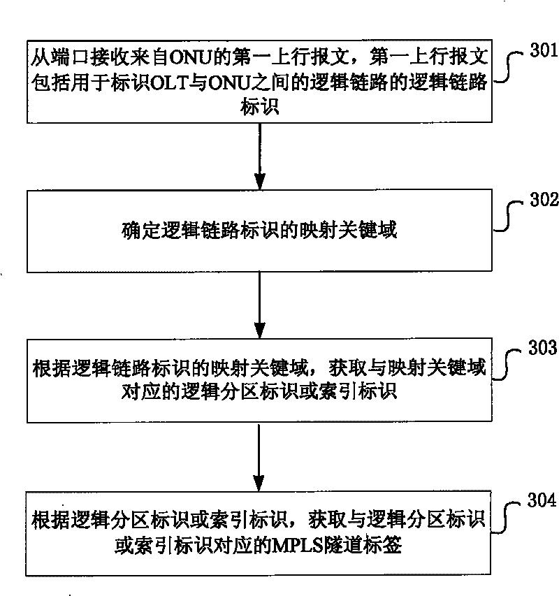
[0048] 103: Acquire the MPLS tunnel label corresponding to the logical link identifier and the first identifier according to the logical link identifier and the first identifier;

[0049] 104: Transmit a second uplink packet on the MPLS tunnel corresponding to the MPLS tunnel label, where the second uplink packet includes the data in the first uplink packet and the MPLS tunnel label.

[0050] Wherein, ...

Embodiment 2

[0223] An embodiment of the present invention provides an optical line terminal, see Figure 4 ,include:

[0224] The first receiving module 1201 is configured to receive a first uplink message from an ONU from a port, the first uplink message includes a logical link identifier for identifying a logical link between the OLT and the ONU;

[0225] The first determining module 1202 is configured to determine a first identifier corresponding to the above-mentioned first uplink message, where the first identifier includes an ONU identifier for identifying an ONU or a port identifier for identifying a port;

[0226] The first acquiring module 1203 is configured to acquire the MPLS tunnel label corresponding to the logical link identifier and the first identifier according to the logical link identifier and the first identifier;

[0227] The first transmission module 1204 is configured to transmit a second uplink packet on the MPLS tunnel corresponding to the MPLS tunnel label, wher...

Embodiment 3

[0243] An embodiment of the present invention provides an optical line terminal, see Figure 5 ,include:

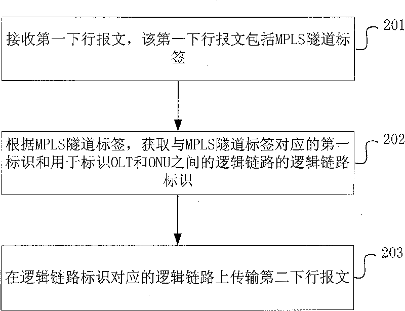
[0244] The second receiving module 1301 is configured to receive a first downlink message, where the first downlink message includes an MPLS tunnel label;

[0245] The second obtaining module 1302 is used to obtain the first identification corresponding to the MPLS tunnel label and the logical link identification used to identify the logical link between the OLT and the ONU according to the MPLS tunnel label. The port identification of the ONU or the ONU identification used to identify the ONU;

[0246] The second transmission module is configured to transmit the second downlink message on the logical link corresponding to the logical link identifier, where the second downlink message includes the data in the first downlink message and the logical link identifier.

[0247] Wherein, the second acquiring module 1302 includes,

[0248] The fourth query unit is used to que...


PUM


Abstract

The invention discloses a method and a system for the transmission of a message in an optical communication system and an optical line terminal, and belongs to the communication field. The method comprises: receiving, from a port, a first uplink message from an ONU, wherein the first uplink message includes a logic link identification; determining a first identification corresponding to the first uplink message, wherein the first identification comprises an ONU identification or a port identification; obtaining an MPLS tunnel label according to the logic link identification and the first identification; and transmitting a second uplink message on an MPLS tunnel corresponding to the MPLS tunnel label, wherein second uplink message comprises the data in the first uplink message and the MPLS tunnel label. The system comprises an optical network unit ONU and an optical line terminal OLT. The invention realizes the mapping between the logic link and the MPLS tunnel by establishing the corresponding relation between the MPLS tunnel and the logic link between the OLT and the ONT, so that the capacity for service configuration is not limited and the flexibility is strong.

Description

technical field [0001] The invention relates to the communication field, in particular to a method, system and optical line terminal for message transmission in an optical communication system. Background technique [0002] As a broadband optical access technology, a passive optical network (Passive Optical Network, PON) adopts a point-to-multipoint topology. PON consists of an Optical Line Terminal (OLT), an Optical Distribution Network (ODN), and one or more Optical Network Units (Optical Network Unit, ONU) / Optical Network Terminals (Optical Network Terminal, ONT). Located in the central office, the OLT is not only a switch or router, but also a multi-service platform; the OLT can provide various WAN interfaces, and can also provide multiple Gigabit Ethernet and 10 Gigabit Ethernet interfaces, providing the second layer and Layer 3 switching and routing functions. ONU / ONT is located on the user side. The difference between ONU and ONT is that ONT is directly located at t...

Claims


Application Information

Patent Timeline
Patent Type & Authority Applications(China)
IPC IPC(8): H04L12/56H04L12/46H04Q11/00H04L12/54H04L45/50
CPCH04Q2011/0077H04L45/50H04Q11/0067H04L12/56
Inventor 李宏宇郑若滨
Owner HUAWEI TECH CO LTD
Why Eureka
Try Eureka