

Let-off device of loom using positive easing mechanism
A technology of loose warp mechanism and loom, which is applied in the direction of loom, weaving, textile and papermaking, etc., and can solve the problems of detection value change and change increase
- Summary
- Abstract
- Description
- Claims
- Application Information
AI Technical Summary
Problems solved by technology
Method used
Image

Examples
Embodiment Construction
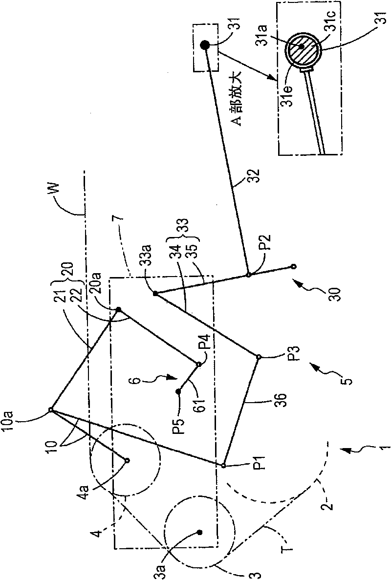
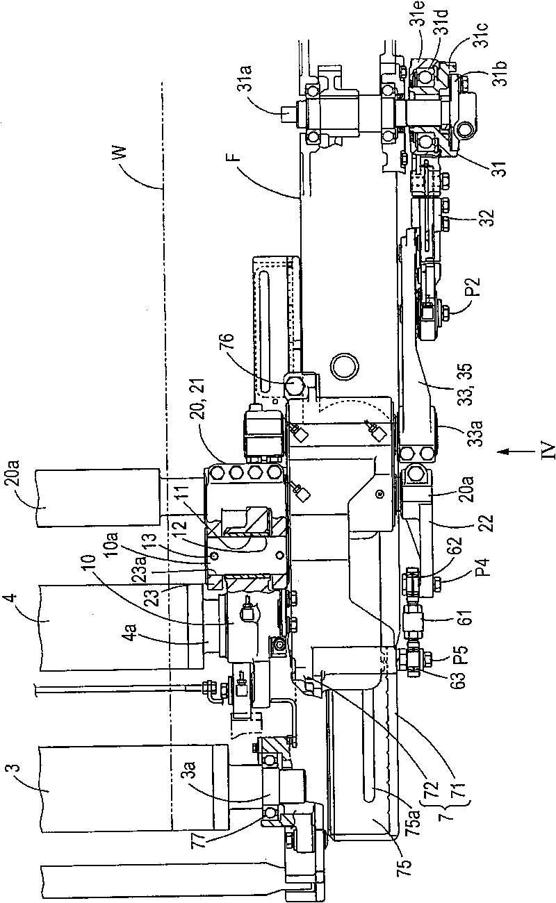
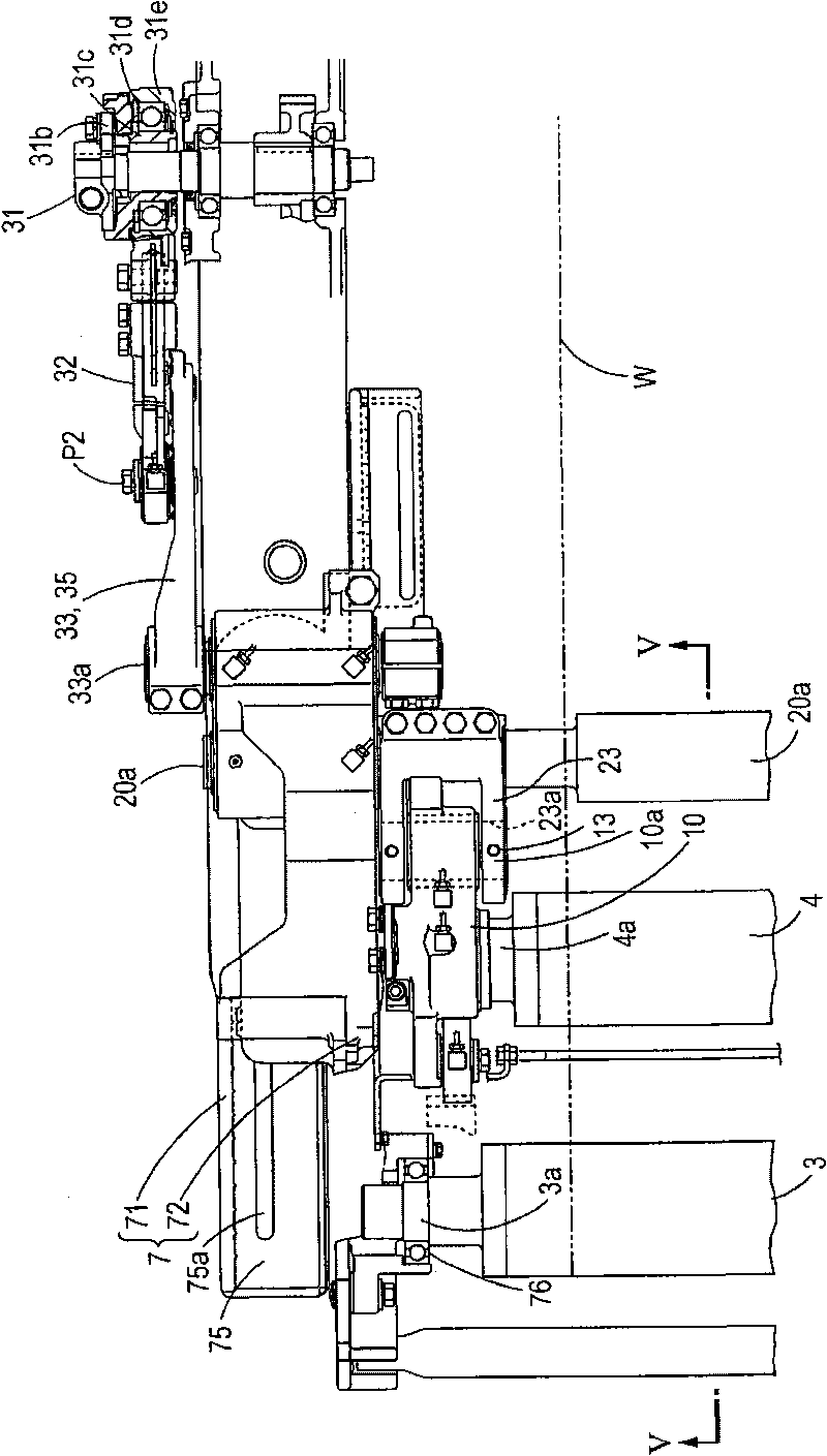
[0046] according to Figure 1 to Figure 5 An example of the let-off device 1 of the loom using the positive easing mechanism 5 will be described. In the following description, the "front-rear direction" refers to the moving direction of the warp yarn according to feeding of the warp yarn. In addition, the take-up device side in the warp direction of the loom is referred to as "front side", and the let-off device 1 side is referred to as "rear side". figure 1 It is an explanatory diagram of the active easing mechanism 5 in the let-off device 1 of the above-mentioned loom. The black dots in the figure are the fulcrums directly or indirectly fixed on the rack. The white dots in the diagram are pivots that are not fixed to the rack. figure 2 It is a plan view of the warp let-off device 1 of the loom, and shows the right side part seen from the rear side. image 3 It is a plan view of the let-off device 1 of the loom, and shows the left side part seen from the rear side. Fi...
PUM
 Abstract
Description
Claims
Application Information