Rotary braiding machine

A technology for knitting machines and yarn carrying discs, which is applied in the field of knitting machines, can solve problems such as reduced work efficiency, high cost, and complex control systems, and achieve the effects of improving work efficiency and reducing failure rates

Active Publication Date: 2010-06-16
阚玉华
View PDF1 Cites 25 Cited by
  • Summary
  • Abstract
  • Description
  • Claims
  • Application Information

AI Technical Summary

Problems solved by technology

However, its disadvantages are: the control system is complex, precise, and costly, and because it needs to stop and turn over every 90 degrees of movement, the work efficiency is greatly reduced, and each turning mechanism must lead out control lines, with the size of the table increase, the difficulty of implementation increases
[0004] In addition, there is also a rotary knitting machine that uses a fixed-shaped track plate to guide the advancement of the yarn-carrying device. Due to the fixed shape of the track plate, a reversing device and a control device must be added at the intersection of the yarn-carrying device. very complicated

Method used


Image

  • Rotary braiding machine
  • Rotary braiding machine
  • Rotary braiding machine

Examples


Embodiment 1

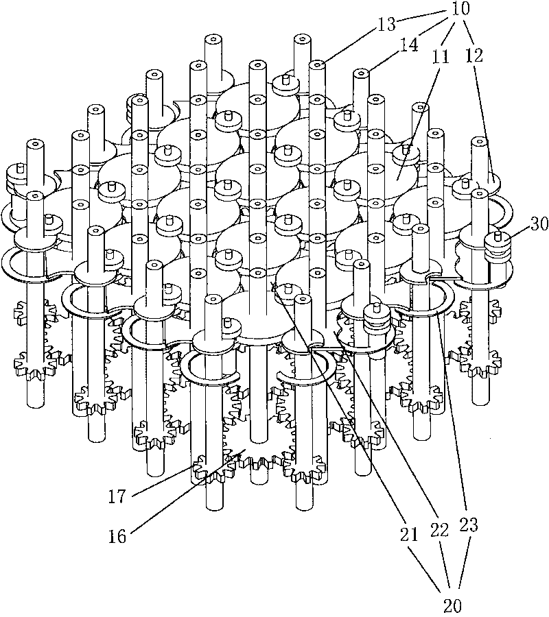
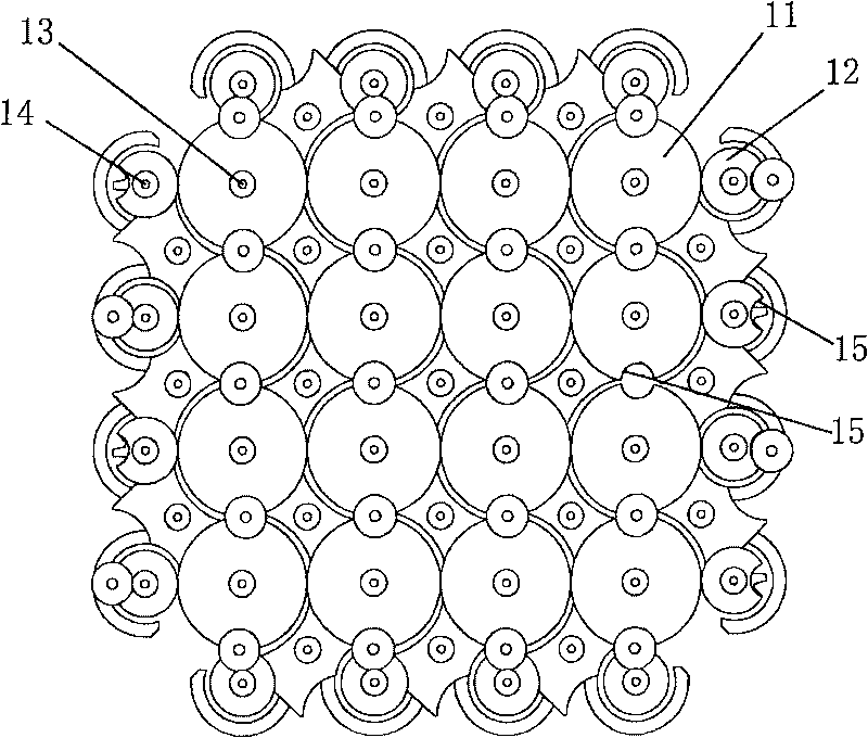
[0050] Such as figure 2 Shown is a schematic perspective view of a preferred embodiment of the rotary knitting machine. It can be seen from the figure that it includes a drive assembly 10, a reversing assembly 20, and a yarn carrying seat 30. The drive assembly 10 includes a determinant arrangement And the yarn carrying discs 11 and 12 that rotate synchronously, the center of the yarn carrying disc 11 can be used for axial yarn (not shown in the figure) to pass through, and the yarn carrying seat 30 is connected with the spindle (not shown in the figure) of the weaving yarn, And it advances under the drive of the yarn-carrying discs 11, 12, and the reversing assembly 20 is arranged on the advancing path of the yarn-carrying seat 30, and continuously adjusts the advancing direction of the yarn-carrying seat 30. The structure of each part will be discussed in detail below.

[0051] combine figure 2 , image 3 As shown, the drive assembly 10 includes an inner yarn-carrying d...

Embodiment 2

[0058] In this embodiment, the knitting path of the yarn-carrying seat 30 is designed as a straight line, which basically adopts all the components and movement methods in Embodiment 1, the difference is that the movable baffle includes an inner baffle 41 and an outer baffle Plate 42, at least two track edges formed on the inner baffle 41 and the outer baffle 42 are linear track grooves, and the combination of the linear track grooves forms the linear motion track of the yarn carrying seat, and the fixed baffle is The fixed track is an arc-shaped track groove formed on the fixed baffle. Specifically:

[0059] Such as Figure 11A , Figure 11B , Figure 11C As shown, the two concave arcs 24 of the inner baffle 41 are changed into the form of two linear track grooves 44, and in order to prevent each inner baffle 41 from interfering when rotating, two opposite sides of the inner baffle 41 are Designed with slope 411 (attached Figure 11C shown). In addition, in order to pre...


PUM


Abstract

The invention provides a rotary braiding machine, comprising a drive assembly, a reversing assembly and a yarn-carrying seat, the drive assembly comprises yarn-carrying disks which are arranged in lines and rows and are rotated simultaneously, the yarn-carrying seat is connected with a yarn-braiding spindle and moves ahead under the drive of the yarn-carrying disks, the reversing assembly comprises moveable partition plates arranged among the lines and rows of the yarn-carrying disks and fixed partition plates arranged on the peripheries of the lines and rows of yarn-carrying disks, at least two rail edges are formed on each moveable partition plate, each moveable partition plate rotates intermittently to form the inner movement locus of the yarn-carrying seat, and fixed rails are arranged on the fixed partition plates to form the automatic retracing movement locus of the yarn-carrying seat on an edge. Therefore, the movement path of a yarn-carrying device can be reliably controlled on a predetermined path so as to reduce the failure rate of the braiding machine, and simultaneously, being matched with special external assemblies, the rotary braiding machine can realize the continuous braiding of a preformed assembly with a needed section shape, thereby increasing the working efficiency and reducing the cost.

Description

technical field [0001] The invention relates to a braiding machine for braiding a three-dimensional preform, in particular to a rotary braiding machine. Background technique [0002] At present, among the three-dimensional weaving methods, there are typically two-step method, four-step method and rotation method, and the rotation method has the advantage of synchronous operation, so the production efficiency is high, and it is the fastest weaving speed among the existing three-dimensional weaving methods. The disadvantage is that there are many moving parts and the control is difficult. [0003] Such as figure 1 As shown, it is a schematic diagram of the table structure of a rotary knitting machine disclosed in US Patent No. 6,439,096. Each yarn carrying disc 91 drives four yarn carrying devices 92 to rotate, and every movement of 90 degrees needs to be stopped, and the precise control of the independent drive is turned over mechanism, the yarn carrying device 92 on the ad...

Claims


Application Information

Patent Timeline
Patent Type & Authority Applications(China)
IPC IPC(8): D04C3/02D04C3/00
Inventor 刘振国阚玉华
Owner 阚玉华
Why Eureka
Try Eureka