Key of optical coded lock

A combination lock and key technology, applied in the field of keys, can solve the problems of cumbersome, inconvenient use for the elderly and children, long passwords, etc., and achieve the effect of convenient use.

Inactive Publication Date: 2010-06-16
方荣光
View PDF2 Cites 17 Cited by
  • Summary
  • Abstract
  • Description
  • Claims
  • Application Information

AI Technical Summary

Problems solved by technology

However, this kind of optical combination lock is generally considered for safety when unlocking, and the password is generally set to ...

Method used


Image

  • Key of optical coded lock
  • Key of optical coded lock
  • Key of optical coded lock

Examples


Embodiment 1

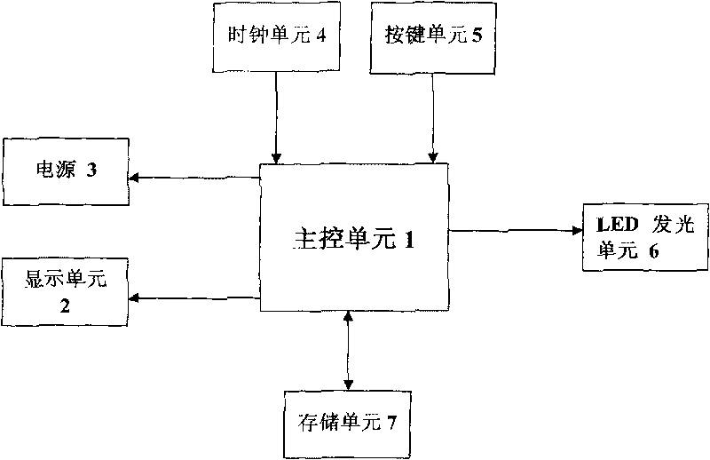
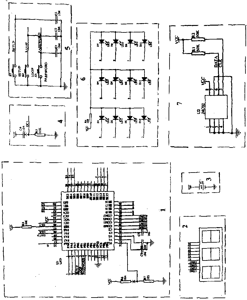
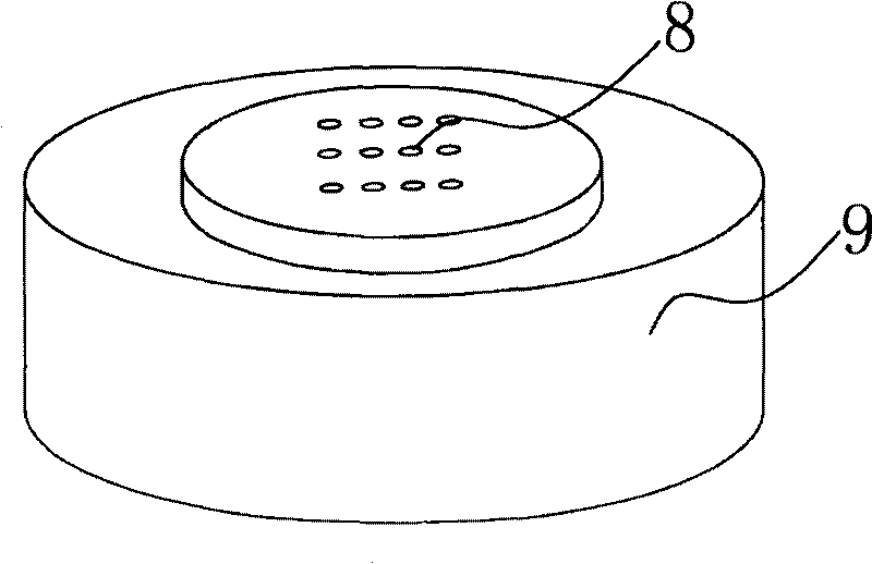
[0023] Embodiment 1: as figure 1 As shown, the optical combination lock key includes a casing, and the casing can be set as a disc cylindrical casing 9; the three buttons arranged on the casing are respectively an unlock / setting key 10, a password setting cycle key 11, and a password change confirmation key 12 buttons, twelve light-emitting holes 8; a lock control switch control device arranged in the casing, the lock control switch control device includes a power supply 3, a clock unit 4, a key unit 5, a main control unit 1, and an LED light emitting unit 6 , display unit 2, storage unit 7, described power supply 3, clock unit 4, key unit 5 are connected with main control unit 1 respectively, and main control unit 1 is connected with LED lighting unit 6, display unit 2, storage unit 7 respectively ; The three buttons on the shell are set corresponding to the key unit 5, and the twelve LED lights on the LED light-emitting unit 6 are matched with the twelve light-emitting holes...

Embodiment 2

[0039] Embodiment 2: The difference between this embodiment and Embodiment 1 is that the casing is set as a U disk-shaped casing 14, such as Figure 5 shown.

Embodiment 3

[0040] Embodiment 3: The difference between this embodiment and Embodiment 1 is that the shell is set to a cylindrical shell 15 cylindrical, such as Image 6 shown.


PUM


Abstract

The invention relates to a key, in particular to a key for an optical coded lock, which is matched with the optical coded lock. The key comprises a shell, a button, a plurality of lightening holes and a lock control switch controlling device, wherein the button and the lightening holes are arranged on the shell; the lock control switch controlling device is arranged in the shell and comprises a power supply, a clock unit, a button unit, a main control unit and an LED lightening unit; the power supply, the clock unit and the button unit are respectively connected with the main control unit; the main control unit is connected with the LED lightening unit; the button on the shell is arranged corresponding to the button unit; and an LED lamp on the LED lightening unit is matched with a plurality of lightening holes on the shell. The invention has the beneficial effect that the key unlocks through remote control by one button and has convenient use, and solves the problems in the prior art that a long code needs to be input once for unlocking every time, is too fussy and easy to forget, and is especially inconvenient for old people and children to use.

Description

technical field [0001] The invention relates to a key, in particular to an optical combination lock key used in conjunction with an optical combination lock. Background technique [0002] The Chinese patents I applied for first: Patent No.: ZL200720004367.6, patent name: optical combination lock; and the Chinese patent for subsequent improvement and improvement of this patent, patent number: ZL200820084414.7, optical combination lock; all have been authorized, and In real life application, this kind of optical combination lock controls the photosensitive resistance electronic password switch through the beam emitting device, thereby controlling the switch of the electronically controlled mechanical lock. This design skillfully combines the switch control part of the beam emitting device The switch is set separately, the electronic parts of the lock are not exposed, and the thief cannot directly touch the electronic part of the lock from the outside, thus avoiding the possibi...

Claims


Application Information

Patent Timeline
IPC IPC(8): E05B19/00E05B49/00E05B37/20
Inventor 方荣光
Owner 方荣光
Why Eureka
Try Eureka