Integral structure of liquid reservoir and oil separator of compressor

A technology of oil separator and liquid storage, which is applied in the direction of refrigeration and liquefaction, machines/engines, and parts of pumping devices for elastic fluids, etc., which can solve the problems of underutilization and reduce manufacturing and use costs, The effect of sufficient heat exchange and improvement of overall efficiency

Active Publication Date: 2013-08-28
SHANGHAI HITACHI ELECTRICAL APPLIANCES CO LTD
View PDF5 Cites 0 Cited by
  • Summary
  • Abstract
  • Description
  • Claims
  • Application Information

AI Technical Summary

Problems solved by technology

However, at present, the liquid reservoir and oil separator of the air conditioner are set separately, which has certain limitations in improving the efficiency of the system, installation space and cost.
Not taking full advantage of the characteristics of both

Method used


Image

  • Integral structure of liquid reservoir and oil separator of compressor
  • Integral structure of liquid reservoir and oil separator of compressor
  • Integral structure of liquid reservoir and oil separator of compressor

Examples


Embodiment Construction

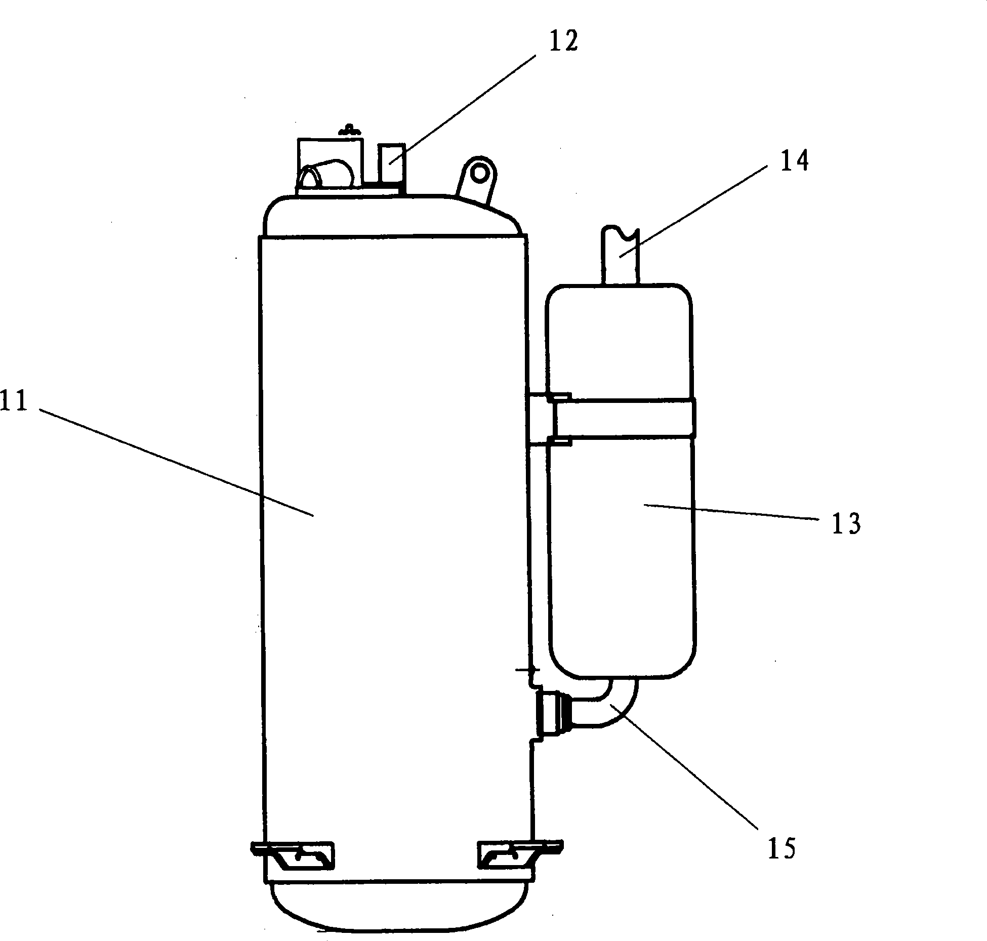
[0019] figure 1 A prior art conventional compressor configuration is shown. The compressor 11 has an exhaust pipe 12 . The liquid reservoir 13 has a suction inlet pipe 14 and a suction outlet pipe 15 . The suction outlet pipe 15 is connected with the compressor, and is used as the suction pipe of the compressor.

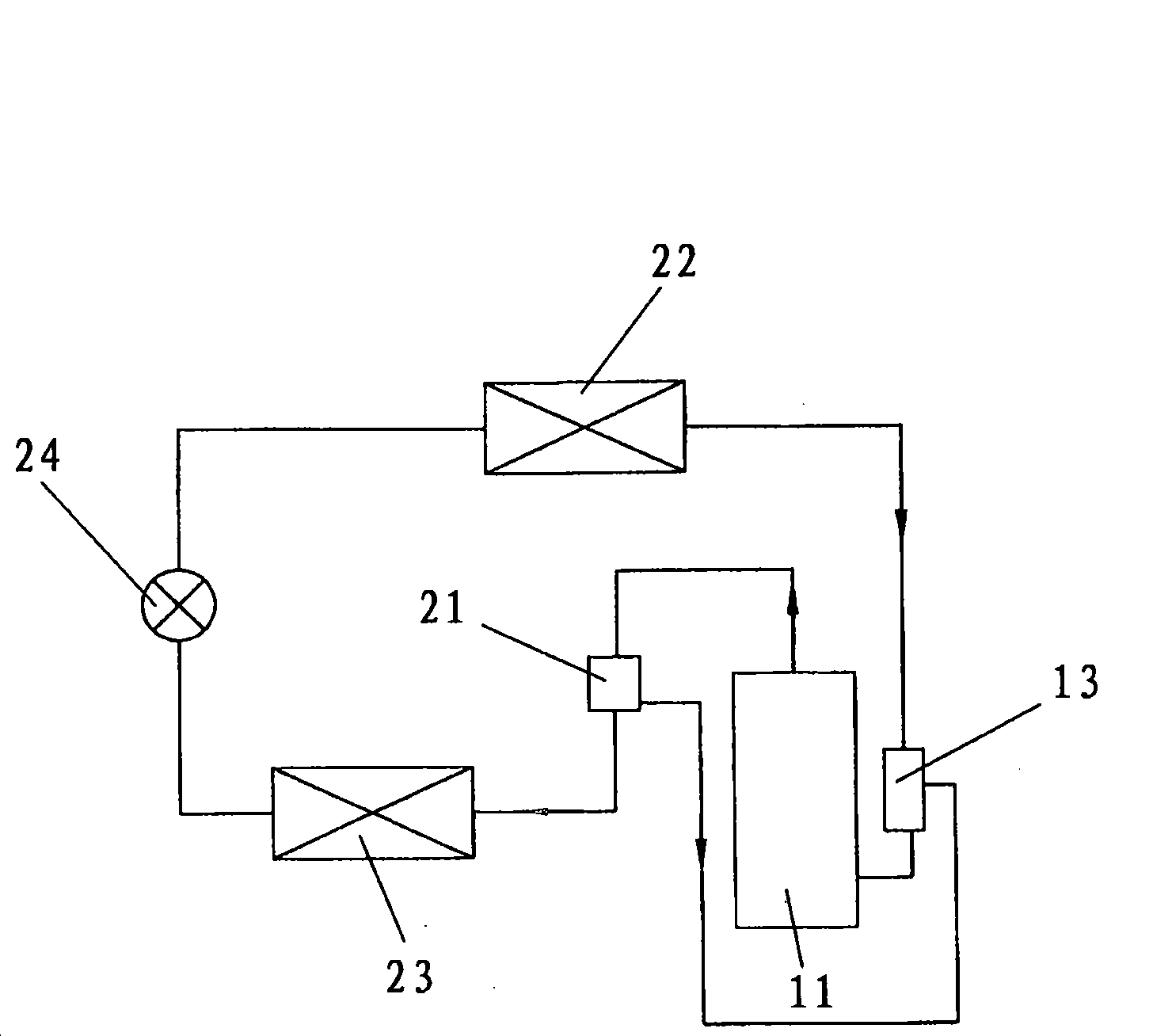
[0020] figure 2 Shows the traditional air conditioning system structure. Such as figure 2 As shown, the structure of a traditional air conditioning system mainly includes a compressor 11, an accumulator 13, an oil separator 21, an evaporator 22, a condenser 23, a throttling device 24 and a series of pipelines. The suction inlet pipe of the liquid receiver 13 is connected with the evaporator, the exhaust inlet pipe of the oil separator 21 is connected with the exhaust pipe of the compressor, and the exhaust outlet pipe of the oil separator 21 is connected with the condenser 23 . The oil separator 21 is also connected with the accumulator 13 to deliver the retu...


PUM


Abstract

The invention relates to an integral structure for a liquid reservoir and an oil separator of a compressor, comprising a casing, an air suction inlet pipe, an air suction outlet pipe, an exhaust inlet pipe, an exhaust outlet pipe, a spiral oil separating pipe and a capillary pipe. The structure is characterized that the casing limits a liquid storing cavity; the air suction inlet pipe and the airsuction outlet pipe extend in and are communicated with the liquid storing cavity; the exhaust inlet pipe and the exhaust outlet pipe extend in the oil separating cavity and are communicated to each other through the spiral oil separating pipe in the liquid storing cavity; exhaust air entering the exhaust inlet pipe exchanges heat with fluid in the liquid storing cavity through the spiral oil separating pipe and then is discharged from the exhaust outlet pipe; the air suction is communicated with lower part of the liquid storing cavity through an oil return hole on the air suction outlet pipe; and the air suction outlet pipe is also provided with a second oil return hole which is communicated with a third oil return hole on the exhaust outlet pipe through the capillary pipe.

Description

technical field [0001] The invention relates to an integrated structure of a liquid accumulator and an oil separator for a compressor. Background technique [0002] All existing air conditioners are equipped with a liquid accumulator, which is used to avoid liquid shock when the refrigerant liquid returns, to ensure that the gas enters the compressor, and to improve the reliability of the compressor. The high-power air-conditioning system is equipped with an oil separator, which is used to separate the refrigerating machine oil in the compressor exhaust, reduce the possibility of oil accumulation in the heat exchanger, and improve the operating efficiency of the air-conditioning system. However, at present, the liquid storage device and the oil separator of the air conditioner are installed separately, which has certain limitations in improving the efficiency of the system, installation space and cost. The characteristics of both are not fully utilized. Contents of the in...

Claims


Application Information

Patent Timeline
Patent Type & Authority Patents(China)
IPC IPC(8): F25B43/02F25B43/00F04C29/02F04C29/00F04B39/00
Inventor 沈建芳丛丽米廷灿
Owner SHANGHAI HITACHI ELECTRICAL APPLIANCES CO LTD
Why Eureka
Try Eureka