
Submersible flashlight capable of floating on the water

A flashlight and barrel body technology, applied in the field of flashlights, can solve problems such as loss of use, inability to float on the water surface, and damage by flooding

Inactive Publication Date: 2010-06-16
刘允钊
View PDF0 Cites 9 Cited by
  • Summary
  • Abstract
  • Description
  • Claims
  • Application Information

AI Technical Summary

Problems solved by technology

[0004] Yet generally existing various flashlight structures, although all can achieve the effect of lighting to provide people with appropriate lighting, but in its actual operation and use, it is found that this type of flashlight structure can only simply emit light for lighting, and it has the following disadvantages: (1) This type of flashlight does not have any waterproof design, which makes it easy for moisture to invade the interior of the flashlight during use, causing the internal circuit of the flashlight and the metal conductive sheet to be damp, rusted or even damaged.
(2) This type of flashlight not only does not have any waterproof design, but also cannot float on the water surface, so that once it falls into the water, it will quickly sink to the bottom, especially for people working on the water surface, flashlights often fall In the water, sink into the bottom of the water, and cannot be picked up or damaged by submersion, resulting in great loss in use
(3) This type of flashlight generally sets the control switch to control its on-off state on the side edge of the body, or directly uses the body and the lampshade seat or the bottom cover to tighten and loosen the flashlight to control the on-off state of the flashlight, so that it can be used to control the flashlight. The design of the blinking control switch does not have the function of waterproof and pressure resistance, so it cannot be used in water

Method used


Image

  • Submersible flashlight capable of floating on the water
  • Submersible flashlight capable of floating on the water
  • Submersible flashlight capable of floating on the water

Examples


Embodiment Construction

[0017] The present invention will be further described below in conjunction with the accompanying drawings.

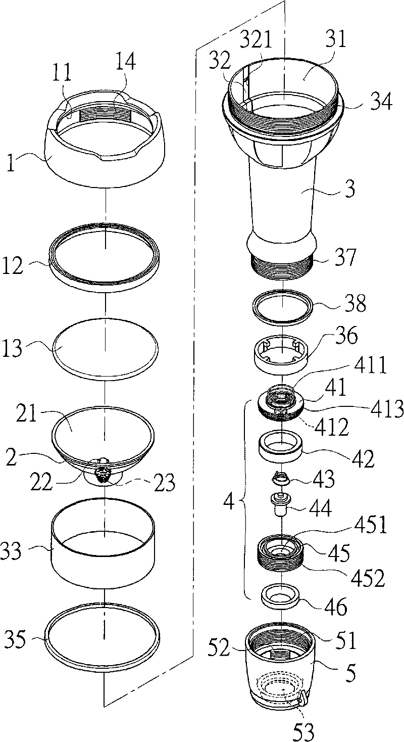
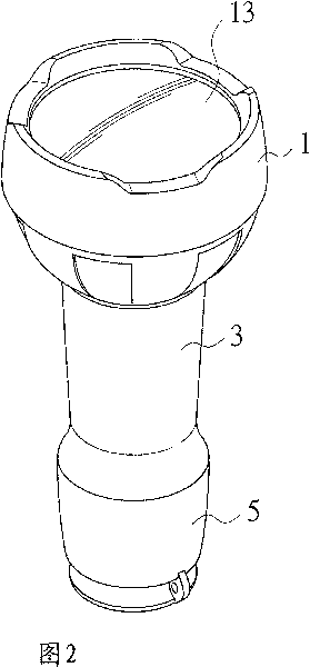
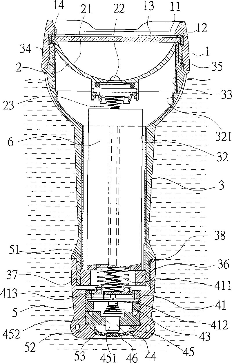
[0018] like figure 1 As shown, a diving flashlight that can float on the water surface includes a front cover 1, a lamp cup 2, a barrel body 3, a switch group 4 and a back cover 5;

[0019] The inner edge of the front end of the front cover 1 is formed with an abutment edge 11, so that a waterproof gasket 12 and a light-transmitting lens 13 can be positioned in the front cover 1, and the waterproof gasket 12 and the light-transmitting lens 13 are against the abutment. At the edge 11, there is also a threaded segment 14 on the inner edge of the front cover 1.

[0020] An optical mirror 21 is formed on the inner edge of the lamp cup 2 , and a light-emitting component 22 is provided in the middle of the lamp cup 2 , and a conductive component 23 is provided corresponding to the light-emitting component 22 at the bottom of the lamp cup 2 .

[0021] The front end of the b...


PUM


Abstract

The invention relates to a submersible flashlight capable of floating on the water, wherein a waterproof gasket and a light-admitting lens which are embedded and positioned inside a front cover, the front end of a cylinder body expands outside to form a holding chamber for holding a lamp cup, a screw thread section on the external edge of the holding chamber is combined with the screw thread of the front cover, a waterproof gasket is sleeved on the inner end of the screw thread section, a waterproof gasket is sleeved on the inner end of a screw thread section formed by the external edge of the bottom end of the cylinder body, the screw thread section is combined with the screw thread of a back cover, the inside of the back cover is provided with a switching group, the outside of the switching group is provided with a waterproof gasket, and the waterproof gasket is combined with the outside of the switching group through a through-hole on the back cover. By adopting the structure, when falling in water, the flashlight can not sink into the water bottom and can float on the water so that the person working above the water can fast and conveniently pick up the flashlight when dropping the flashlight, and the person who falls in water and is in danger can use the flashlight for calling for help.

Description

technical field [0001] The invention relates to a flashlight, in particular to a flashlight capable of floating on water. Background technique [0002] In the current existing technology, in daily life, there are often opportunities for temporary lighting, such as: suddenly entering a dark room and cannot find the light switch for a while, or suddenly turning off the power in the room at night, or unlocking the door at night, Or looking for things in the dark, etc., all need an immediate light source, so as to immediately improve the inconvenience caused at that time. [0003] Generally, the existing common flashlight structure is mainly composed of a main body, a lampshade base and a bottom cover. There is a light-emitting component inside the top of the body, and the battery is used as the main source for the light-emitting component to shine, and a switch part is used to control the light-emitting component. Turn on or off the lighting function, and the battery in the bo...

Claims


Application Information

Patent Timeline
Patent Type & Authority Applications(China)
IPC IPC(8): F21L4/00F21V23/04F21V31/00
CPCF21W2111/10F21L4/00B63C11/02F21V31/005F21L4/005F21V15/01F21V23/0421
Inventor 刘允钊
Owner 刘允钊
Learn More