
Novel movable type beacon device

A mobile light tower, a new type of technology, is applied in the direction of portable lighting devices, lighting devices, lighting device components, etc. It can solve the problems of inflexible height adjustment of light poles, restrictions on application occasions, and changing lighting directions, etc., to achieve a small footprint , easy to operate and use, flexible adjustment effect

Active Publication Date: 2010-06-16
FUJIAN ROBUST POWER
View PDF1 Cites 21 Cited by
  • Summary
  • Abstract
  • Description
  • Claims
  • Application Information

AI Technical Summary

Problems solved by technology

Although the mobile lighthouse is easy to move and has high lighting brightness, the height adjustment of the light pole is not flexible enough, and the lighthouse and the frame are relatively fixed, so that the lighting direction cannot be changed when the frame does not move. Therefore, the application occasions are limited.

Method used


Image

  • Novel movable type beacon device
  • Novel movable type beacon device
  • Novel movable type beacon device

Examples


Embodiment Construction

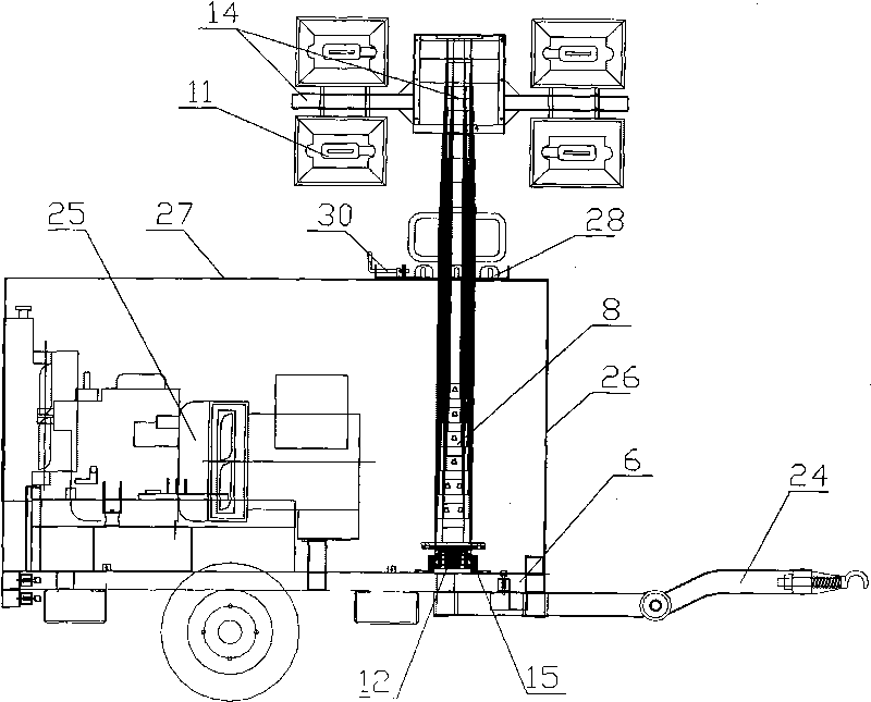
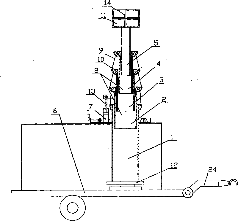
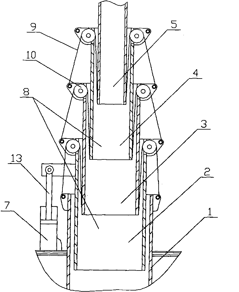
[0011] Novel mobile lighthouse device of the present invention, as figure 1 , 2 As shown, it includes a movable vehicle frame 6, and the movable vehicle frame 6 is provided with a generator set 25, a lamp frame 14 provided with a lamp 11, and a lifting light pole 8, and the lifting light pole 8 includes a bottom-to-bottom Several sections of connecting rods are sequentially socketed on the upper section, and the previous section of connecting rods is sequentially inserted into the inner cavity of the next connecting rod, and can slide along the inner cavity of the next connecting rod. In order to realize the step-by-step rise of each connecting rod, a steel wire rope 9 is connected to the lower part of the (N+1) connecting rod, and the steel wire rope 9 is connected to the ( N-1) on the connecting rod, wherein, N is an integer greater than or equal to 2. In order to facilitate the adjustment of the lighting direction, the first connecting rod 1 is rotatably connected with th...


PUM


Abstract

The invention relates to a novel movable type beacon device which comprises a movable vehicle frame, wherein the movable vehicle frame is provided with a generating unit, a lamp holder with a lamp and a lifting type lamp post. The novel movable type beacon device is characterized in that the lifting type lamp post comprises a plurality of sections of connecting rods which are sequentially sleeved from bottom to top; the previous sections of connecting rods are sequentially inserted into inner cavities of the next sections of connecting rods and can slide and shift along the inner cavities of the next sections of connecting rods; the lower part of the (N+1) section of connecting rod is connected with a steel rope; the steel rope is downwards connected to the (N-1) section of connecting rod after passing around a pulley beside the upper part of the N section of connecting rod; the first section of connecting rod is rotatably connected with the movable vehicle frame by a rotating seat which is arranged at the bottom; a power drive mechanism for driving the second section of connecting rod to lift is vertically arranged beside the first section of connecting rod; and the lamp holder is arranged at the upper end of the topmost section of connecting rod. The device has flexible adjustment of height and direction of illumination, strong on-site adaptability, simple structure and good use effect.

Description

technical field [0001] The invention relates to a novel mobile light tower device. Background technique [0002] When working in emergency, disaster relief, construction and other occasions at night, large-area, high-brightness temporary light source equipment is required to provide lighting. At present, the commonly used solution is to temporarily set up lighthouses and install lamps, but this method not only takes a long time to build, but also has poor adaptability to the site. If there is no power facility near the site, cables must be pulled over long distances, and the height, aspect, and angle of the lighting must be adjusted. difficulty. Some mobile light towers have also appeared on the existing market, as the Chinese patent application number 200720118922.8 discloses a mobile light tower, including a lamp panel assembly (1), and a lifting rod (2) connected to the lamp panel assembly (1). ), a power supply device for providing power to the lamp panel assembly (1),...

Claims


Application Information

Patent Timeline
IPC IPC(8): F21L13/00F21V19/02F21W131/402
Inventor 萧绍端
Owner FUJIAN ROBUST POWER
Learn More