Camera module, electronic device including the same, and method for positioning lenses of camera module

A positioning method and camera technology, which is applied to the camera body, TV, camera, etc., can solve the problems of large thrust and spring deformation, and achieve high-precision positioning

Active Publication Date: 2010-06-16
SHARP KK
View PDF2 Cites 27 Cited by
  • Summary
  • Abstract
  • Description
  • Claims
  • Application Information

AI Technical Summary

Problems solved by technology

As a result, there are problems in that a large thrust is required, and since the amount of deformation of the spring becomes large, a large strain is imparted to the spring, etc.

Method used


Image

  • Camera module, electronic device including the same, and method for positioning lenses of camera module
  • Camera module, electronic device including the same, and method for positioning lenses of camera module
  • Camera module, electronic device including the same, and method for positioning lenses of camera module

Examples


Embodiment Construction

[0082] Below, based on Figure 1 to Figure 14 , Figure 16 ~ Figure 20 Embodiments of the present invention will be described.

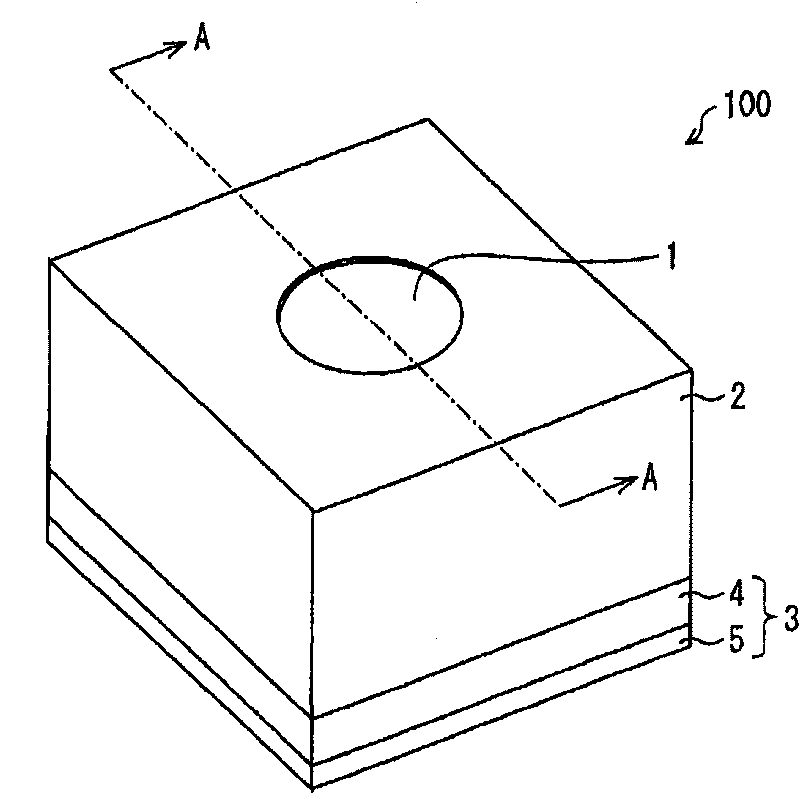
[0083] figure 1 It is a perspective view of the camera module of this embodiment. The camera module 100 includes: an optical unit 1 as an imaging optical system; a lens driving device (lens driving unit) 2 that drives the optical unit 1 ; and an imaging unit 3 that photoelectrically converts light passing through the optical unit 1 . The optical unit 1 is held inside the lens driving device 2 . The imaging unit 3 is configured to include a sensor unit 4 and a substrate 5 on which the sensor unit 4 is mounted. The camera module 100 is configured by laminating the sensor unit 4 and the lens driving device 2 sequentially in the optical axis direction on the substrate 5 . In the following description, for convenience, the side of the optical unit 1 is referred to as the upper side, and the side of the imaging unit 3 is referred to as the lower side...


PUM


Abstract

The invention relates to a camera module, an electronic device including the same, and a method for positioning lenses of the camera module. In the camera module, the position of image pickup lenses at an end at infinity is defined by contact between a bottom surface of a lens barrel and a surface of a sensor cover. This makes it possible to realize a camera module having image pickup lenses positioned with a high degree of accuracy.

Description

technical field [0001] 本发明涉及在便携式电话等电子设备中搭载的摄影机模块、摄影机模块用透镜的定位方法,其中,特别涉及在透镜驱动部安装摄像透镜时,不需要进行利用螺丝的位置调整的摄影机模块的结构和透镜的定位方法。 Background technique [0002] 近年来,在便携式电话等的电子设备搭载利用透镜驱动装置发挥自动聚焦功能的摄影机模块的例子不断增加。在透镜驱动装置中,存在利用步进电动机的类型、利用压电元件的类型、VCM(Voice CoilMotor:音圈电动机)类型等各种类型,已经在市场上流通。 [0003] 在对这样的透镜驱动装置固定透镜的情况下,当不正确地设定对于摄像元件的透镜的光轴方向的初始位置时,由于散焦而变为模糊的图像。在不使透镜移动的固定焦点型摄影机模块中,通过对摄像元件或保持摄像元件的构件直接安装透镜或保持透镜的透镜支持器,能够谋求上述透镜的初始位置的高精度化(例如,参照专利文献1等)。 [0004] 专利文献1:日本专利申请特开2003-046825号公报(2003年2月14日公开) [0005] 专利文献2:日本专利申请特开2008-197313号公报(2008年8月28日公开) [0006] 本发明要解决的课题 [0007] 可是,在具备自动聚焦功能的摄影机模块中,由于摄像透镜的安装精度低,产生需要初始聚焦调整的问题。 [0008] 具体地,在具备通过透镜驱动装置使透镜在光轴方向上移动的自动聚焦功能的摄影机模块中,在透镜驱动装置安装有透镜或透镜支持器。在该情况下,在透镜的初始位置的设定时,加上了透镜驱动装置的组装误差(从透镜驱动装置的安装基准面到透镜安装基准面的累积误差)。因此,不调整该组装误差,安装透镜就极其困难。由此,为了调整该组装误差,需要初始聚焦调整。 [0009] 即,利用步进电动机或压电元件的透镜驱动装置,能够较大地设定光轴方向的行程(stroke)。因此,预先进行一边对装入有摄像透镜的透镜驱动装置的可动部进行驱动,一边寻找在无限远(INF)的对焦位置的初始聚焦调整。然后,将调整后的对焦位置作为INF基准位置。进而,通过从INF基准位置进一步驱动透镜,也寻找在微距状态下的对焦位置,作为微距(macro)基准位置。由此,在无限远侧、和微距...

Claims


Application Information

Patent Timeline
Patent Type & Authority Applications(China)
IPC IPC(8): G02B7/04G02B7/09H04N5/225G02B7/02G03B17/02H04N5/335
CPCH04N5/2254G02B7/023
Inventor 关本芳宏石末义人海冈真司
Owner SHARP KK
Why Eureka
Try Eureka