
Liquid crystal display having embedded resistor-type control structure

A liquid crystal display, resistive technology, used in static indicators, instruments, electrical digital data processing and other directions, can solve the problems of decreased light transmittance, impaired display effect, increased assembly workload, etc., to improve the accuracy of touch pressure degree of effect

Inactive Publication Date: 2010-06-16
CHI HSIN ELECTRONICS CORP
View PDF0 Cites 11 Cited by
  • Summary
  • Abstract
  • Description
  • Claims
  • Application Information

AI Technical Summary

Problems solved by technology

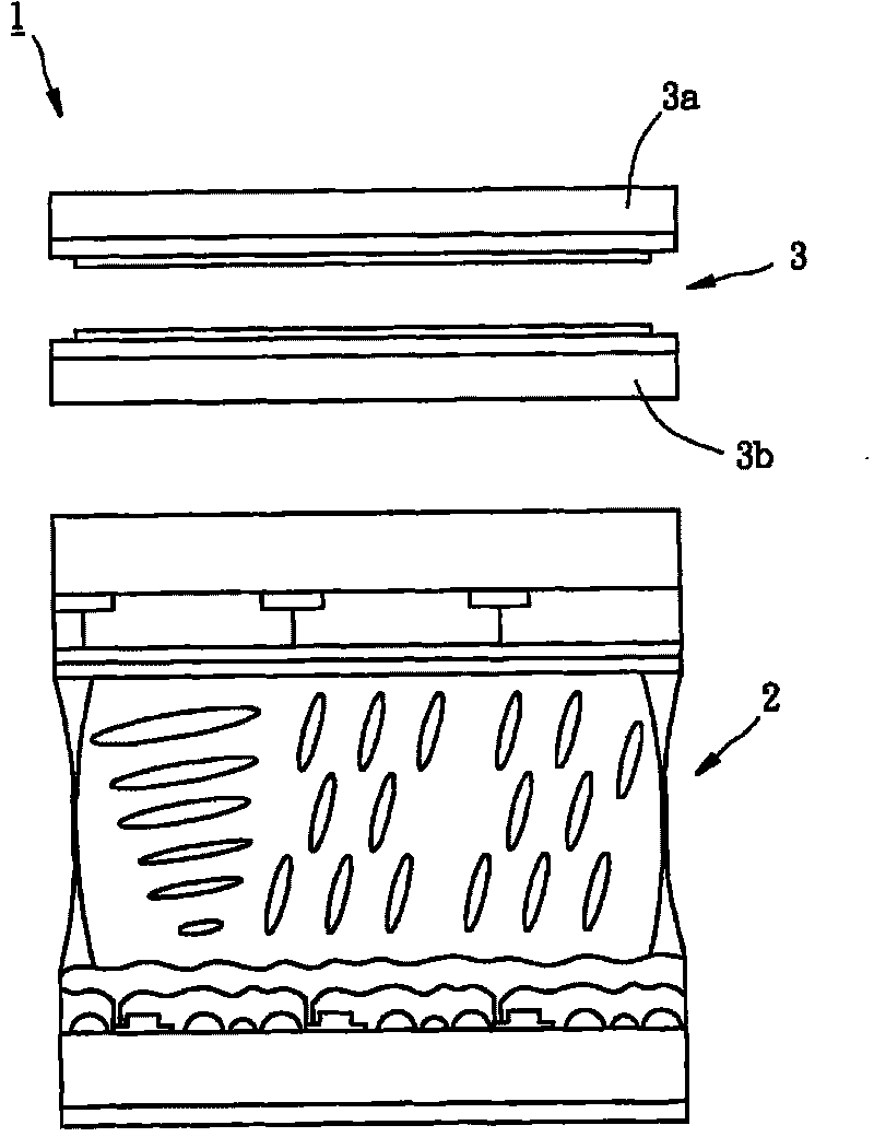
[0002] Currently, a liquid crystal display 1 with a touch function is mainly composed of a liquid crystal display panel 2 and a touch panel 3 bonded together. As a result, the overall thickness and weight of the liquid crystal display 1 increase, and this situation is obviously contrary to the trend of liquid crystal displays in the direction of thinner and smaller. Secondly, the touch panel 3 is stacked on the top of the liquid crystal display panel 2 in a bonding manner. , but this lamination process will increase the burden of assembly work. Furthermore, since the touch panel 3 is arranged on the side close to the viewer, when the display light source passes through the touch panel 3, it will still cause light penetration. The transmittance decreases, which further damages the display effect. In view of this, the inventor of this case expects to improve the above-mentioned deficiency. Based on many years of research experience in optical displays, the present invention is finally produced.

Method used


Image

  • Liquid crystal display having embedded resistor-type control structure
  • Liquid crystal display having embedded resistor-type control structure
  • Liquid crystal display having embedded resistor-type control structure

Examples


Embodiment Construction

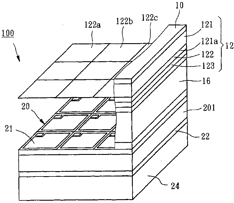
[0047] Figure 2 to Figure 5 It is a liquid crystal display 100 with an embedded resistive touch structure according to the present invention. The structure of the liquid crystal display 100 includes an upper polarizer 10, a pair of counter electrode substrates 12, a liquid crystal layer 16, and a thin film transistor array substrate from top to bottom. 20. A polarizing plate 22 and a backlight module 24, wherein:

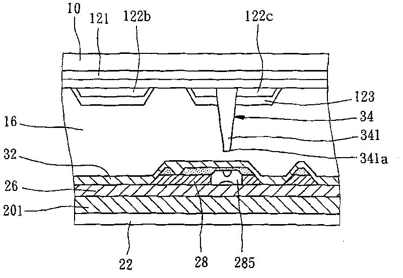
[0048] The counter electrode substrate 12 includes a glass substrate 121, a color filter layer 122 disposed on a surface 121a of the glass substrate 121, and a transparent electrode 123 covering the color filter layer 122. The color filter layer 122 is composed of multiple The red, green and blue filter units 122a, 122b and 122c are arranged in sequence.

[0049] The thin film transistor array substrate 20 includes a glass substrate 201, a plurality of gate lines 202 arranged in parallel along a first direction D1, and a plurality of source lines 203 arranged in p...


PUM


Abstract

The invention provides a liquid crystal display having an embedded resistor-type control structure. A liquid crystal layer is arranged between a film transistor array substrate and an opposite electrode substrate; a plurality of first detection lines is formed through the same process as a gate line of the film transistor array substrate and is parallel to the gate line; a plurality of second detection lines is formed through the same process as a source line of the film transistor array substrate and is parallel to the source line; a patterning first insulating layer is arranged for electrically separating the source line and the second detection lines from the gate line and the first detection lines; a plurality of punches is provided, of which openings at two ends correspond to a first conducting side of the first detection lines and a second conducting side of the second detection lines respectively; and a plurality of lugs correspond to the punches. A resistor impedance effect is produced when the lugs drives the first conducting side to contact with the second conducting side after the lugs are pressed so as to judge the position of a contact point.

Description

technical field [0001] The present invention relates to a liquid crystal display, more specifically, a liquid crystal display with an embedded resistive touch structure. Background technique [0002] Currently, a liquid crystal display 1 with a touch function is mainly composed of a liquid crystal display panel 2 and a touch panel 3 bonded together. As a result, the overall thickness and weight of the liquid crystal display 1 increase, and this situation is obviously contrary to the trend of liquid crystal displays in the direction of thinner and smaller. Secondly, the touch panel 3 is stacked on the top of the liquid crystal display panel 2 in a bonding manner. , but this lamination process will increase the burden of assembly work. Furthermore, since the touch panel 3 is arranged on the side close to the viewer, when the display light source passes through the touch panel 3, it will still cause light penetration. The transmittance decreases, which further damages the disp...

Claims


Application Information

Patent Timeline
Patent Type & Authority Applications(China)
IPC IPC(8): G02F1/133G02F1/1362G06F3/045
Inventor 赖辉龙
Owner CHI HSIN ELECTRONICS CORP
Learn More