Method and system for implementing synchronous Ethernet based on clock recovery and public reference sources

A common reference and clock recovery technology, applied in transmission systems, synchronization devices, digital transmission systems, etc., can solve problems such as deterioration of TDM voice and data service transmission quality, service interruption, and insufficient Ethernet timing synchronization capabilities, to ensure clock Synchronize the process to facilitate the realization of the effect of the process

Inactive Publication Date: 2010-06-16
ZTE CORP
View PDF3 Cites 16 Cited by
  • Summary
  • Abstract
  • Description
  • Claims
  • Application Information

AI Technical Summary

Problems solved by technology

[0002] In the prior art, the purpose of synchronous Ethernet is to solve the problem of insufficient timing synchronization capability of Ethernet to meet the needs of mobile wireless access network solutions.
[0003] With the convergence of networks, IP technology has more and more obvious advantages in new network construction, and has become the direction of future development convergence; however, in the process of convergence, it also faces a major challenge: due to technology, many applications on the network have inherent timing requirements that rely on network synchronization
[0004] However, different business applications have different requirements for clock synchronization. When traditional fixed-line TDM (TimeDivision Multiplexing) services are carried over Ethernet, if the clocks at both ends of the bearer network are inconsistent, it is easy to cause slippage, resulting in TDM voice and data service transmission quality deterioration, or even service interruption

Method used


Image

  • Method and system for implementing synchronous Ethernet based on clock recovery and public reference sources
  • Method and system for implementing synchronous Ethernet based on clock recovery and public reference sources
  • Method and system for implementing synchronous Ethernet based on clock recovery and public reference sources

Examples


Embodiment Construction

[0025] Various preferred embodiments of the present invention will be described in more detail below in conjunction with the accompanying drawings.

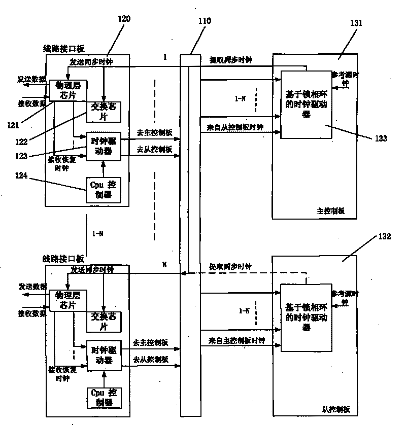
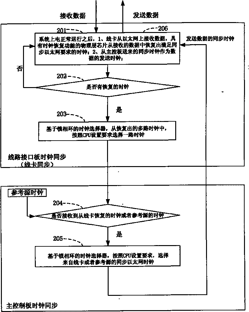
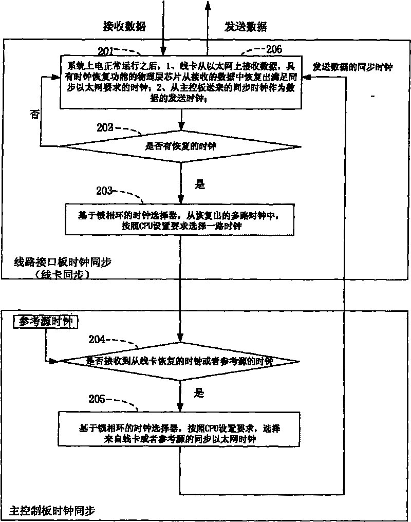
[0026] Such as figure 1 As shown, in the synchronous Ethernet implementation method and system based on clock recovery and public reference source of the present invention, under the control of the CPU controller of the main control board, select recovery from the physical link received by the line card, that is, the line interface board One of the N synchronous clocks, the BITS clock of the main control board, and the synchronous clock (N+1+1) provided by another main control board meets the quality requirements. As a synchronous clock, the synchronous clock is output and distributed For the physical link layer chip of the line card, the physical link layer chip on each line card uses the synchronous clock sent by the main control board as the reference clock (line card synchronization) of the transmission link; the line card pa...


PUM


Abstract

The invention discloses a method and a system for implementing a synchronous Ethernet based on clock recovery and public reference sources. The method comprises the following steps that: a plurality of line interface boards receive data from the Ethernet, recover clock signals meeting the requirement of the synchronous Ethernet through physical chips of the line interface boards, and send the clock signals to a main control board; the main control board selects a path of synchronous clock to be output to the line interface boards through a phase-locked loop-based clock driver according to a plurality of received recovered clock signals; and the line interface boards send the data according to the synchronous clock selected by the main control board. The method and the system for implementing the synchronous Ethernet based on the clock recovery and public reference sources ensure the clock synchronizing process of the synchronous Ethernet because the clock synchronizing operation and corresponding functional modules of the line interface boards and the main control board are adopted, and are convenient for the implementing process of each related service function.

Description

technical field [0001] The invention relates to a method and system for realizing synchronous Ethernet in the field of communication, in particular to a method and system for solving the problem of insufficient timing synchronization capability of the Ethernet. Background technique [0002] In the prior art, the purpose of synchronous Ethernet is to solve the problem of insufficient timing synchronization capability of the Ethernet, so as to meet the needs of mobile wireless access network solutions. [0003] With the convergence of networks, IP technology has more and more obvious advantages in new network construction, and has become the direction of future development convergence; however, in the process of convergence, it also faces a major challenge: due to technology, many applications on the network have inherent timing requirements that depend on network synchronization. [0004] However, different business applications have different requirements for clock synchron...

Claims


Application Information

Patent Timeline
Patent Type & Authority Applications(China)
IPC IPC(8): H04L7/00H04L12/28
Inventor 陈军
Owner ZTE CORP
Why Eureka
Try Eureka