
Carrier power sharing method in multi-carrier cell

A carrier power and multi-carrier technology, applied in power management, network planning, electrical components, etc., can solve the problems of low cell power utilization, inability to use surplus power, waste of carrier surplus power, etc., and achieve the effect of improving utilization

Inactive Publication Date: 2010-06-16
TD TECH COMM TECH LTD
View PDF3 Cites 18 Cited by
  • Summary
  • Abstract
  • Description
  • Claims
  • Application Information

AI Technical Summary

Problems solved by technology

Currently, each carrier can only use the transmit power configured for itself, and cannot use the remaining power of other carriers
This method of not sharing power between carriers leads to low cell power utilization: the remaining power of the carrier that uses less power is wasted, and the carrier that is in urgent need of power cannot use the remaining power of other carriers

Method used

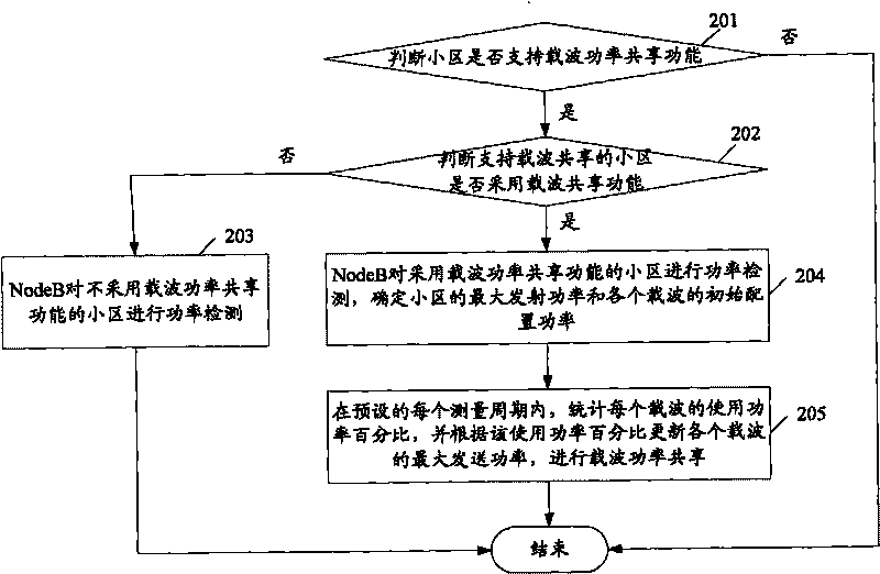

Image

  • Carrier power sharing method in multi-carrier cell
  • Carrier power sharing method in multi-carrier cell
  • Carrier power sharing method in multi-carrier cell

Examples


Embodiment Construction

[0024] In order to make the purpose, technical means and advantages of the present invention clearer, the present invention will be further described in detail below in conjunction with the accompanying drawings.

[0025] The basic idea of ​​the present invention is: to count the power usage status of each carrier, and for the carrier with higher power usage rate, allow it to use the remaining power of the carrier with lower power usage rate.

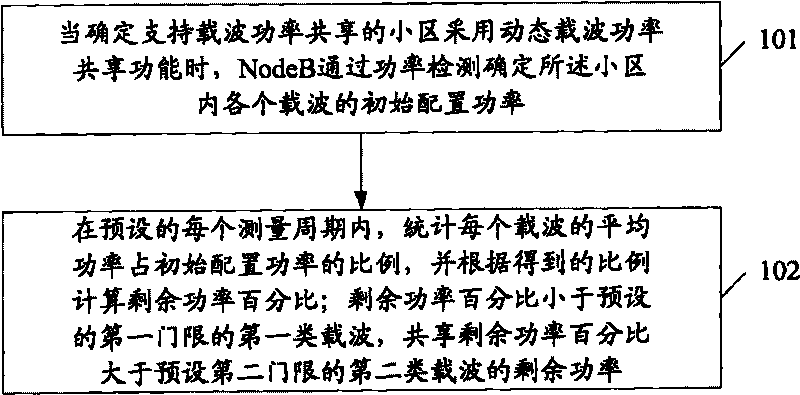
[0026] figure 1 It is an overall flowchart of the carrier power sharing method in the present invention. Such as figure 1 As shown, the method includes:

[0027] Step 101, for a cell supporting carrier power sharing, when it is determined that the cell adopts a dynamic carrier power sharing function, the NodeB determines the initial configuration power of each carrier in the cell through power detection.

[0028] Step 102, in each preset measurement period, count the ratio of the average power of each carrier to the initial configura...


PUM


Abstract

The invention discloses a carrier power sharing method in a multi-carrier cell, which comprises the following steps: when determining that the cell supporting carrier power share adopts a dynamic carrier power sharing function, determining the initial configuration power of each carrier in the cell through a Node B by detecting the power; in each preset measurement period, calculating the proportion of the average power of the carriers to the initial configuration power, and calculating the surplus power percentage according to the acquired proportion; and the first carrier of which the surplus power percentage is smaller than a preset first threshold shares the surplus power of the second carrier of which the surplus power percentage is greater than a preset second threshold. The method can increase the utilization rate of cell power.

Description

technical field [0001] The invention relates to the problem of power usage in a wireless communication system, in particular to a carrier power sharing method in a multi-carrier cell. Background technique [0002] In a multi-carrier cell, the RNC configures the maximum transmit power of the cell and the maximum transmit power of each carrier. Currently, each carrier can only use the transmit power configured for itself, and cannot use the remaining power of other carriers. This method of not sharing power between carriers results in low cell power utilization: the remaining power of a carrier that uses less power is wasted, while a carrier that is in urgent need of power cannot use the remaining power of other carriers. Contents of the invention [0003] In view of this, the present invention provides a carrier power sharing method, which can improve the utilization rate of cell power. [0004] To achieve the above object, the present invention adopts the following techn...

Claims


Application Information

Patent Timeline
Patent Type & Authority Applications(China)
IPC IPC(8): H04W16/14H04W52/36
CPCY02B60/50
Inventor 魏立梅佟学俭刑立军
Owner TD TECH COMM TECH LTD
Learn More