
Method and apparatus for signal discovery

A signal and signal receiving technology, applied in broadcasting devices, pulse modulation TV signal transmission, image communication, etc., can solve the problem that scanning is not one-time

Active Publication Date: 2010-06-16
BRITISH BROADCASTING CORP
View PDF3 Cites 11 Cited by
  • Summary
  • Abstract
  • Description
  • Claims
  • Application Information

AI Technical Summary

Problems solved by technology

However, in reality the scan is not a one-time

Method used


Image

  • Method and apparatus for signal discovery
  • Method and apparatus for signal discovery
  • Method and apparatus for signal discovery

Examples


Embodiment Construction

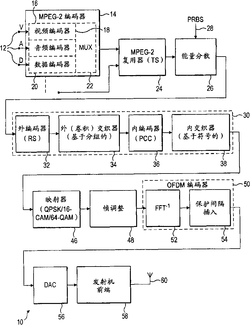
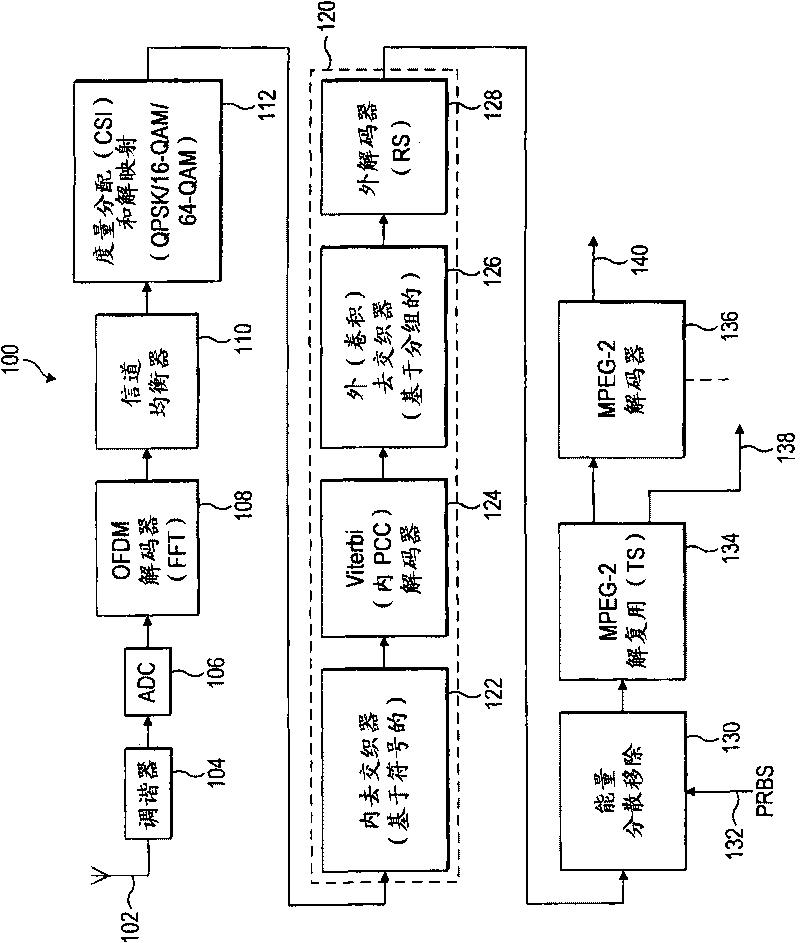
[0033] Preferred embodiments are realized as DVB transmitters, receivers and corresponding systems. In order to be able to understand the present invention, first refer to figure 1 and figure 2 The principle of DVB-T transmitter and receiver is described. refer to image 3 and Figure 4 , describes the basic structure of USDS symbols and the functional components for receiving such signals containing such symbols. Then, refer to Figure 5 and Figure 6 A first embodiment of the invention with USDS notation and means for receiving such a signal is described. refer to Figure 7 and Figure 8 , describes a second preferred embodiment of the USDS symbol and means for receiving such a signal. Figure 9 The effect of so-called dangerous delays is shown and how this embodiment improves in this regard. At last, Figure 10 Another possible receiver arrangement is shown. To avoid repetition, refer to figure 1 and figure 2 Parts of the described transmitter and receiver a...


PUM


Abstract

A system for determining the presence of, and information about, a DVB-T2 signal comprises means for providing a symbol with an active portion, providing a repetition portion and frequency shifting the repetition portion with respect to the active portion at a transmitter. At a receiver, the signal is multiplied by a complex conjugate of a delayed version of the signal to recover the symbol. The symbol may be referred to as a unique signal discovery symbol.

Description

technical field [0001] The present invention relates to a method and apparatus for improved "discovery" of received signals. By "discovery" means: determining the existence of a signal and information about that signal. Background technique [0002] COFDM (Orthogonal Coded Frequency Division Multiplexing) technology can be used for the transmission of any digital information and is well known to those skilled in the art. In short, in COFDM, data is spread over a large number (typically over 1000) of closely spaced carriers. This explains the "frequency division multiplexing" part of the COFDM name. Only a small portion of the data is carried on each carrier, and this greatly reduces the effects of inter-symbol crosstalk. [0003] The distribution of data over many carriers means that selective fading causes some bits to be received incorrectly while others are received correctly. By using error correcting codes, which add extra data bits at the transmitter, multiple or a...

Claims


Application Information

Patent Timeline
Patent Type & Authority Applications(China)
IPC IPC(8): H04L27/26H04N7/00H04N5/00
CPCH04L27/2607H04N21/2383H04L27/2656H04N21/4384H04L27/2657H04H20/95H04N21/42607H04H40/27H04N21/4382H04L27/0012H04L27/2662H04N7/24
Inventor J·H·斯托特
Owner BRITISH BROADCASTING CORP
Learn More