Apparatus and methods for fluorescence imaging using radiofrequency-multiplexed excitation

a fluorescence imaging and radiofrequency multiplication technology, applied in the field of optical imaging devices and methods, can solve the problems of pixel crosstalk, the maximum full-frame (512512 pixels) rate, and the time resolution of fluorescence microscopy has not kept up with the advances in spatial resolution, etc., to achieve the effect of immune to pixel crosstalk

Active Publication Date: 2016-08-23
RGT UNIV OF CALIFORNIA
View PDF15 Cites 104 Cited by
  • Summary
  • Abstract
  • Description
  • Claims
  • Application Information

AI Technical Summary

Benefits of technology

[0017]Acousto-optic deflectors are used to frequency-encode the simultaneous excitation of an entire row of pixels, which enables detection and de-multiplexing of fluorescence images using a single photomultiplier tube and digital phase-coherent signal recovery techniques.
[0019]In one embodiment, the FIRE system is adapted to provide a scalable approach to high-speed imaging, in that it leverages the MHz bandwidths available to radiofrequency (RF) electronics and acousto-optic devices to enable MHz-equivalent pixel clock readout of hundreds of pixels simultaneously in a single data stream. Additionally, FIRE microscopy uses direct digital synthesis (DDS) to engineer the amplitude and phase of each individual pixel excitation frequency, which enables application of phase-coherent digital lock-in amplifier and orthogonal frequency-division multiplexing (OFDM) algorithms to the image de-multiplexing process in order to reduce image noise and pixel crosstalk. The system flexibility afforded by the use of direct digital synthesis enables full adjustment of the pixel number, readout rate, and field of view.
[0024]In combination with fast fluorescent indicators and voltage-sensitive dyes, this high speed imaging modality has the potential to observe previously temporally-unresolved sub-millisecond dynamics in biology, which may lead to a more complete understanding of neural function, autoimmune diseases, cardiac arrhythmias, and other millisecond-timescale biological phenomena.

Problems solved by technology

However, time resolution in fluorescence microscopy has not kept pace with advances in spatial resolution.
While a number of fluorescence microscopy modalities exist, the time resolution of the technique is fundamentally limited by the relatively weak optical emission of fluorescent samples.
As a result, the maximum full-frame (512×512 pixels) rate of traditional single-point laser scanning fluorescence microscopy is limited to approximately a video rate of 30 frames per second, which corresponds to pixel rates of less than 10 MHz.
Linescan and spinning disk confocal microscopes are capable of higher frame rates by multiplexing the fluorescence excitation and detection, but the frame rates are ultimately limited by the low electronic gain and both the optical throughput of the spinning disk and read-out time of the detector, respectively.
While each of these devices present distinct advantages and tradeoffs between sensitivity, speed, resolution, and confocality, a device for imaging the sub-millisecond biochemical dynamics in live cells and in vivo remains an outstanding technical challenge.
Conventional imaging flow cytometers use time delay and integration CCD techniques in order to circumvent this issue, but the serial readout strategy of this approach limits the device to a throughput of 5,000 cells per second.
At this rate, high efficacy detection of rare cells using flow cytometry, such as circulating tumor cells in blood, is not practical for clinical applications.
The tradeoff between speed and sensitivity is a significant limiting factor in high-speed fluorescence microscopy systems.
While modern EMCCDs exhibit high quantum efficiency and gain, the gain register and pixel readout strategy is serial, which limits its overall full frame rate to fewer than 100 frames per second.
PMT's offer higher gain, lower dark noise, and higher readout speed than EMCCDs, but are typically not manufactured in large array formats, limiting their utility to single-point-scanning applications.
Due to the use of a PMT detector, laser scanning fluorescence microscopy is capable of high sensitivity at similar frame rates to EMCCDs, but the serial nature of the beam scanning ultimately limits the speed of image acquisition.

Method used


Image

  • Apparatus and methods for fluorescence imaging using radiofrequency-multiplexed excitation
  • Apparatus and methods for fluorescence imaging using radiofrequency-multiplexed excitation
  • Apparatus and methods for fluorescence imaging using radiofrequency-multiplexed excitation

Examples


example 1

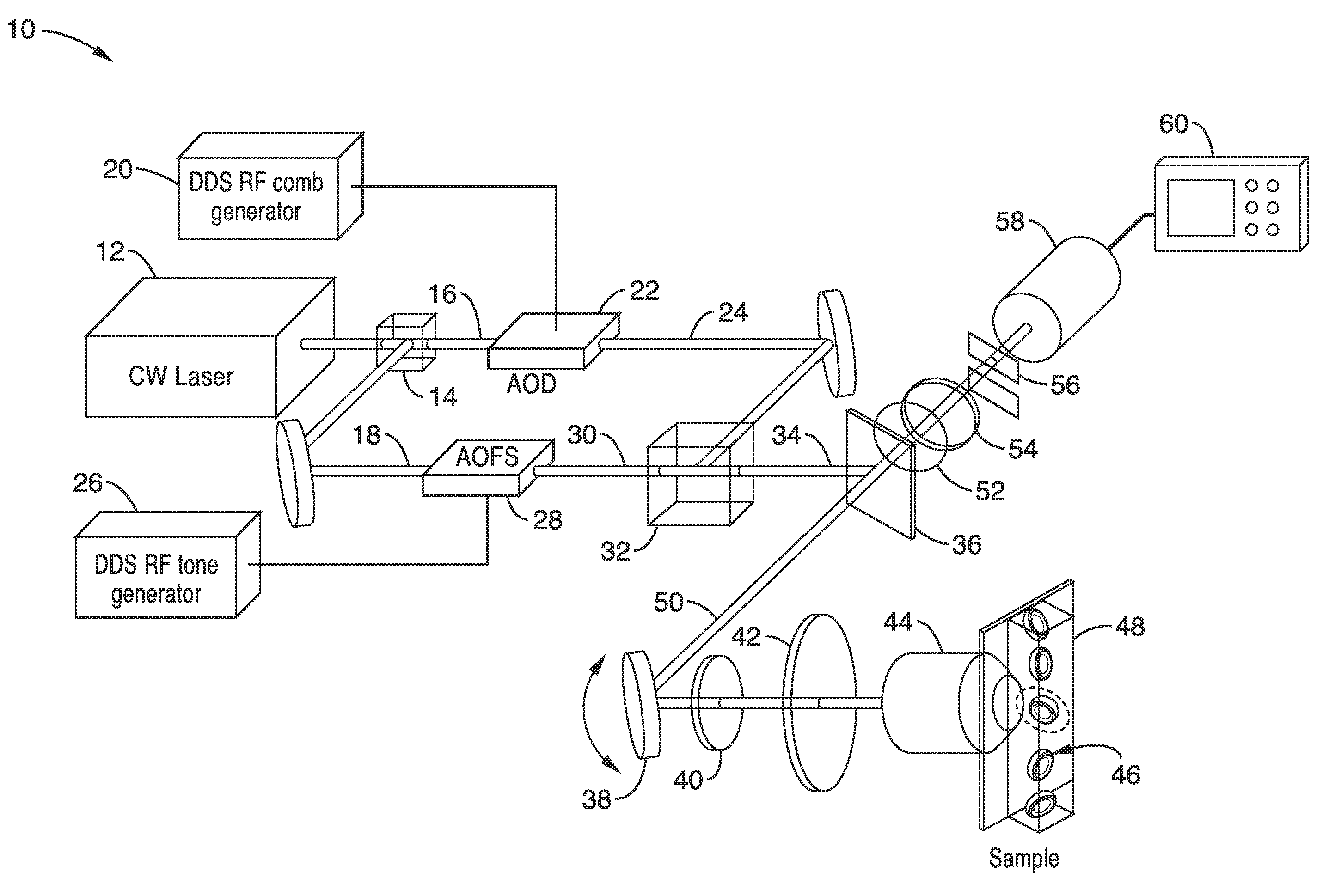
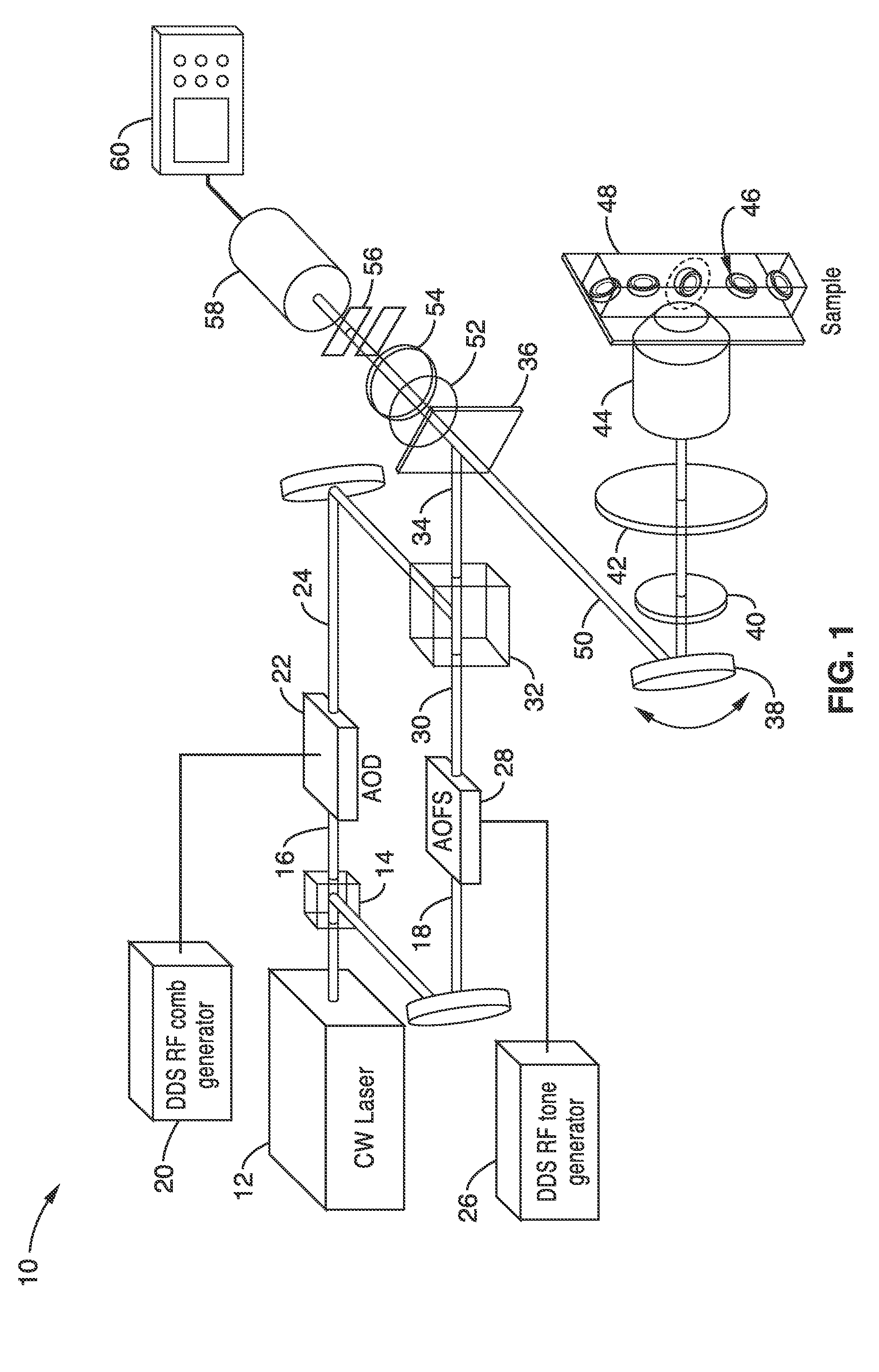
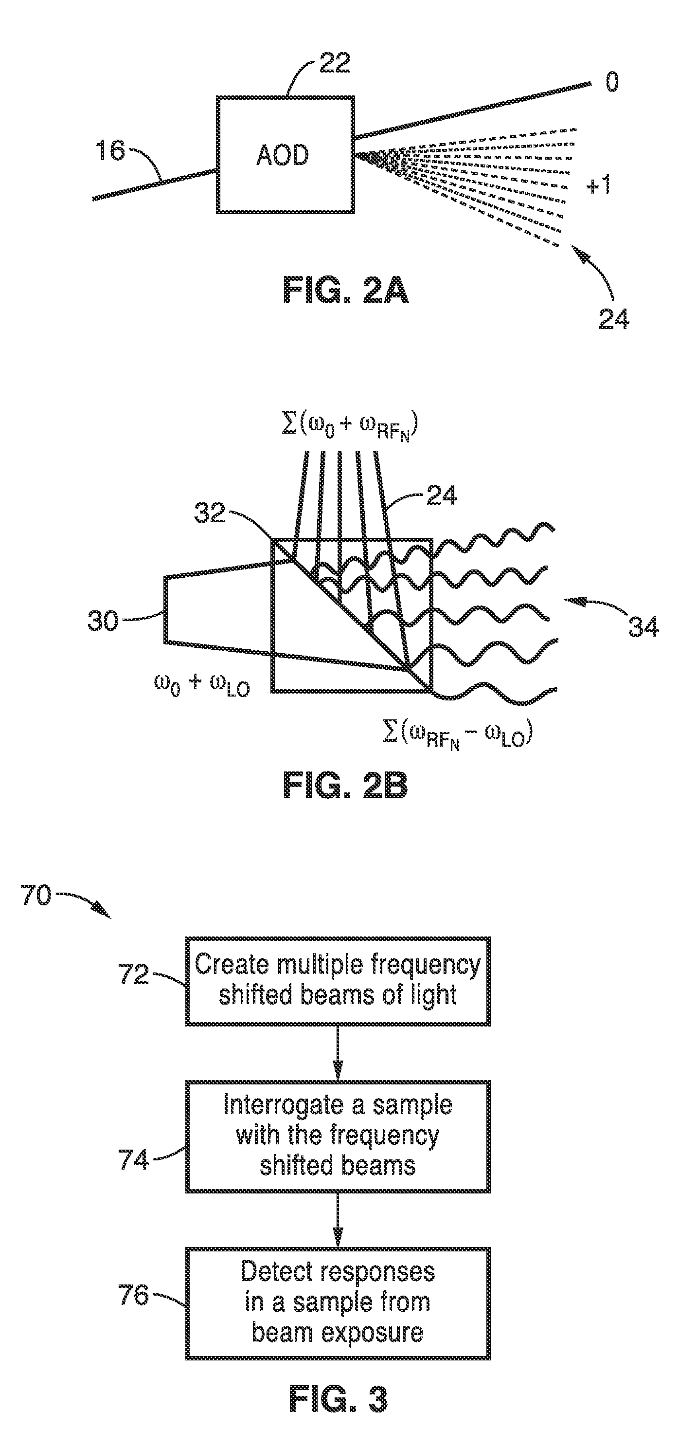
[0081]In order demonstrate the operational principles of FIRE microscopy, a sample of immobilized 15-μm diameter fluorescent polystyrene beads were imaged using 256 excitation frequencies spaced by 300 kHz (total bandwidth of 76.8 MHz). The images were collected at a frame rate of 4.2 kHz. The detected time-domain PMT signal offers no indication of the lateral bead location. A fast Fourier transform (FFT) of three windows of the signal was used to indicate the different frequency components associated with the positions of each bead.

[0082]This illustrated the frequency-to-space mapping of the sample excitation and emission. The vertical location of the beads in the image was recovered from the reference output of the resonant scan mirror. To avoid nonlinear space-to-time mapping from the resonant scan mirror in the vertical direction, an aperture is placed in the intermediate image plane to limit the sample excitation to the linear portion of the scan field, and a sine correction al...

example 2

[0086]To demonstrate FIRE microscopy on biological samples, adherent cells stained with various fluorophores were imaged at a frame rate of 4.4 kHz. NIH 3T3 mouse embryonic fibroblasts, C6 astrocyte rat glial fibroblasts and Saccharomyces cerevisiae yeast were stained with a fluorescent cytosol stain (Calcein AM) or nucleic acid stain (Syto16). NIH 3T3 and MCF-7 cells and C6 astrocytes were propagated in Dulbecco's Modified Eagle Medium with 10% fetal bovine serum and 1% penicillin streptomycin at 37° C. and 5% CO2. Liquid cultures of Saccharomyces cerevisiae were grown in tryptic soy broth at 240 rpm and 37° C.

[0087]Prior to staining, cultured mammalian cells were released from culture flasks, seeded on glass slides, and allowed to spread for 24 hours. Mammalian cells were stained with either 4 μM Syto16 green fluorescent nucleic acid stain in phosphate buffered saline (PBS) for 30 minutes, 1 μM Calcein Red-Orange AM in culture media for 45 minutes, or 1 μM Calcein AM in culture me...

example 3

[0092]Flow cytometry is an application that requires high-speed fluorescence measurements. Compared to single-point flow cytometry, imaging flow cytometry provides information that can be particularly useful for high-throughput rare cell detection. The high flow velocities associated with flow cytometry demand fast imaging shutter speeds and high-sensitivity photodetection to generate high-SNR, blur-free images. Conventional imaging flow cytometers use time delay and integration CCD technology to circumvent this issue, but the serial pixel readout strategy of this technology currently limits devices to a throughput of approximately 5,000 cells per second.

[0093]To demonstrate high-speed imaging flow cytometry using FIRE, a single stationary line scan of 125 pixels spaced by 800 kHz (pixel readout rate of 100 MHz, line scan rate of 800 kHz) was used to image Syto16-stained MCF-7 human breast carcinoma cells flowing in a microfluidic channel at a velocity of 1 m s−1. Assuming a cell di...


PUM

PropertyMeasurementUnit
frequenciesaaaaaaaaaa
velocityaaaaaaaaaa

Abstract

Apparatus and methods for fluorescence imaging using radiofrequency multiplexed excitation. One apparatus splits an excitation laser beam into two arms of a Mach-Zehnder interferometer. The light in the first beam is frequency shifted by an acousto-optic deflector, which is driven by a phase-engineered radiofrequency comb designed to minimize peak-to-average power ratio. This RF comb generates multiple deflected optical beams possessing a range of output angles and frequency shifts. The second beam is shifted in frequency using an acousto-optic frequency shifter. After combining at a second beam splitter, the two beams are focused to a line on the sample using a conventional laser scanning microscope lens system. The acousto-optic deflectors frequency-encode the simultaneous excitation of an entire row of pixels, which enables detection and de-multiplexing of fluorescence images using a single photomultiplier tube and digital phase-coherent signal recovery techniques.

Description

CROSS-REFERENCE TO RELATED APPLICATIONS[0001]This application is a 35 U.S.C. §111(a) continuation of PCT international application number PCT / US2014 / 010928 filed on Jan. 9, 2014, incorporated herein by reference in its entirety, which claims priority to, and the benefit of, U.S. provisional patent application Ser. No. 61 / 750,599 filed on Jan. 9, 2013, incorporated herein by reference in its entirety. Priority is claimed to each of the foregoing applications.[0002]The above-referenced PCT international application was published as PCT International Publication No. WO 2014 / 110290 on Jul. 17, 2014, which publication is incorporated herein by reference in its entirety.STATEMENT REGARDING FEDERALLY SPONSORED RESEARCH OR DEVELOPMENT[0003]This invention was made with Government Support under: W81XWH-10-1-0518, awarded by the U.S. Army, Medical Research and Materiel Command. The Government has certain rights in the invention.INCORPORATION-BY-REFERENCE OF MATERIAL SUBMITTED IN A COMPUTER PRO...

Claims


Application Information

Patent Timeline
Patent Type & Authority Patents(United States)
IPC IPC(8): G01N21/64G02B21/16
CPCG01N21/6458G02B21/16G01N21/6486G01N2021/6419G01N2201/06113G02F1/11G01N21/05G01N21/6408G01N2021/6415G02B21/0076G02B21/0084G02B27/1006
Inventor DIEBOLD, ERIC D.JALALI, BAHRAMBUCKLEY, BRANDON
Owner RGT UNIV OF CALIFORNIA
Why Eureka
Try Eureka