Very low intermediate frequency image rejection receiver with image interference detection and avoidance

a receiver and intermediate frequency technology, applied in the field of radio frequency receivers, can solve the problems of not achieving cost savings, reducing costs, and forming a very large unwanted dc component in the receiver, so as to minimize the amount of power in the image band, minimize the amount of interference, and mitigate image interference.

Inactive Publication Date: 2005-06-30
2201028 ONTARIO
View PDF14 Cites 23 Cited by
  • Summary
  • Abstract
  • Description
  • Claims
  • Application Information

AI Technical Summary

Benefits of technology

[0010] Embodiments of the present invention provide an apparatus and method for mitigating image interference using VLIF architecture. Instead of only trying to maximize rejection, the invention minimizes the amount of power in the image band. Thus, the method can be used independently, or in conjunction with maximizing rejection.

Problems solved by technology

However, direct conversion receivers and very low IF receivers reduce costs by eliminating both a relatively high performance, and therefore, expensive, surface acoustic wave band-pass filter (for allowing the wanted IF signal to pass while blocking all unwanted IF signal enabling channels) and one of the two radio frequency local oscillators (LO) required in super-heterodyne receivers.
However, such receivers suffer from the formation of a very large unwanted DC component interfering with the base-band signal.
However, the cost savings is not achieved without problems such as spurious responses due to interference at the image frequency.
A principal difficulty in implementing a VLIF architecture is the design of an image rejection receiver with sufficient attenuation to reject the image.
Front end filters, although effective for image rejection super-heterodyne architectures, due to the higher first IF, do not provide sufficient attenuation at VLIF image frequencies.
To sufficiently reject the image, image reject mixers often employ complex tuning systems with feedback.
Hence, an unaddressed need exists in the art to address the aforementioned deficiencies and inadequacies.

Method used


Image

  • Very low intermediate frequency image rejection receiver with image interference detection and avoidance
  • Very low intermediate frequency image rejection receiver with image interference detection and avoidance
  • Very low intermediate frequency image rejection receiver with image interference detection and avoidance

Examples


Embodiment Construction

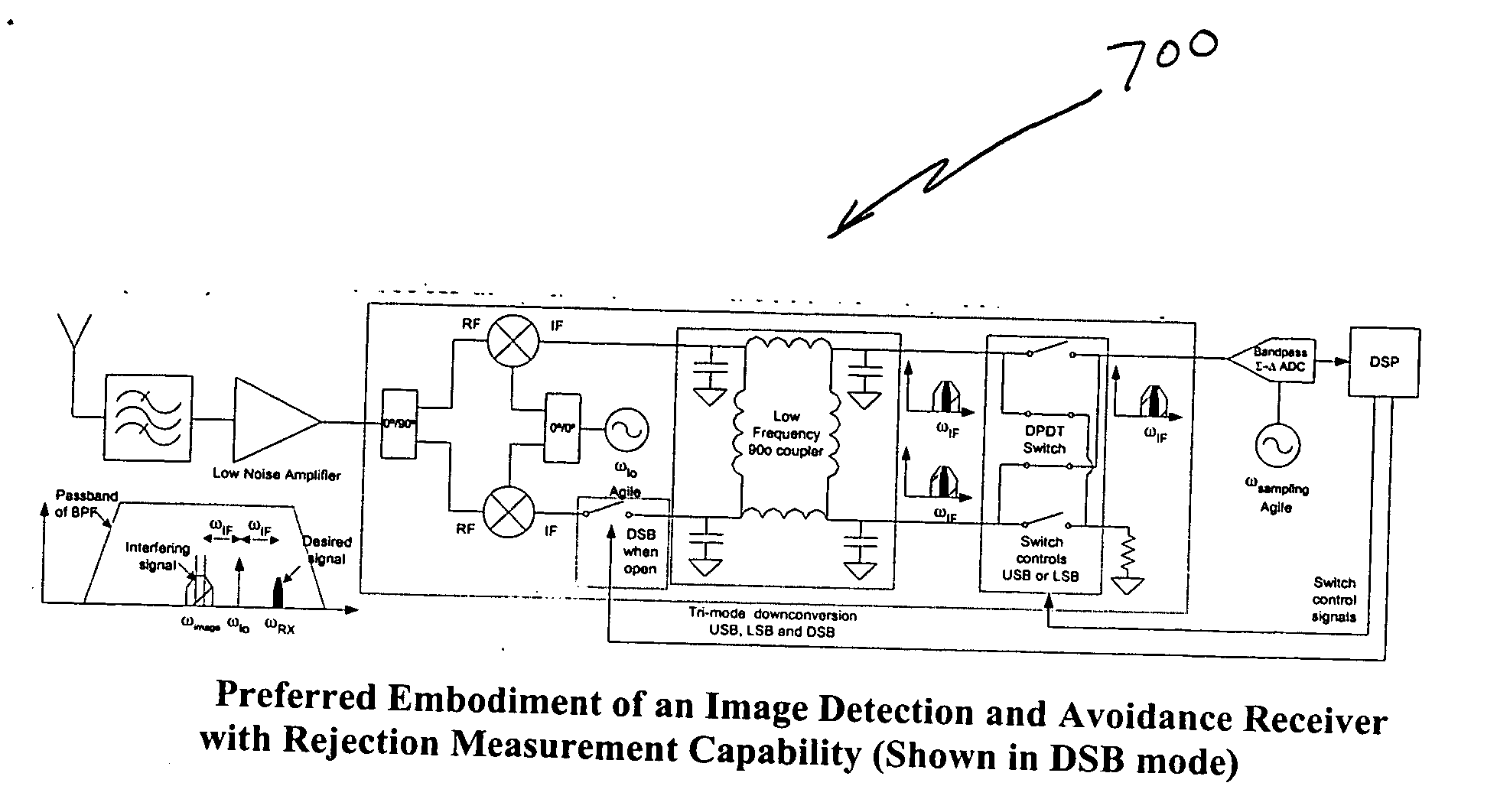
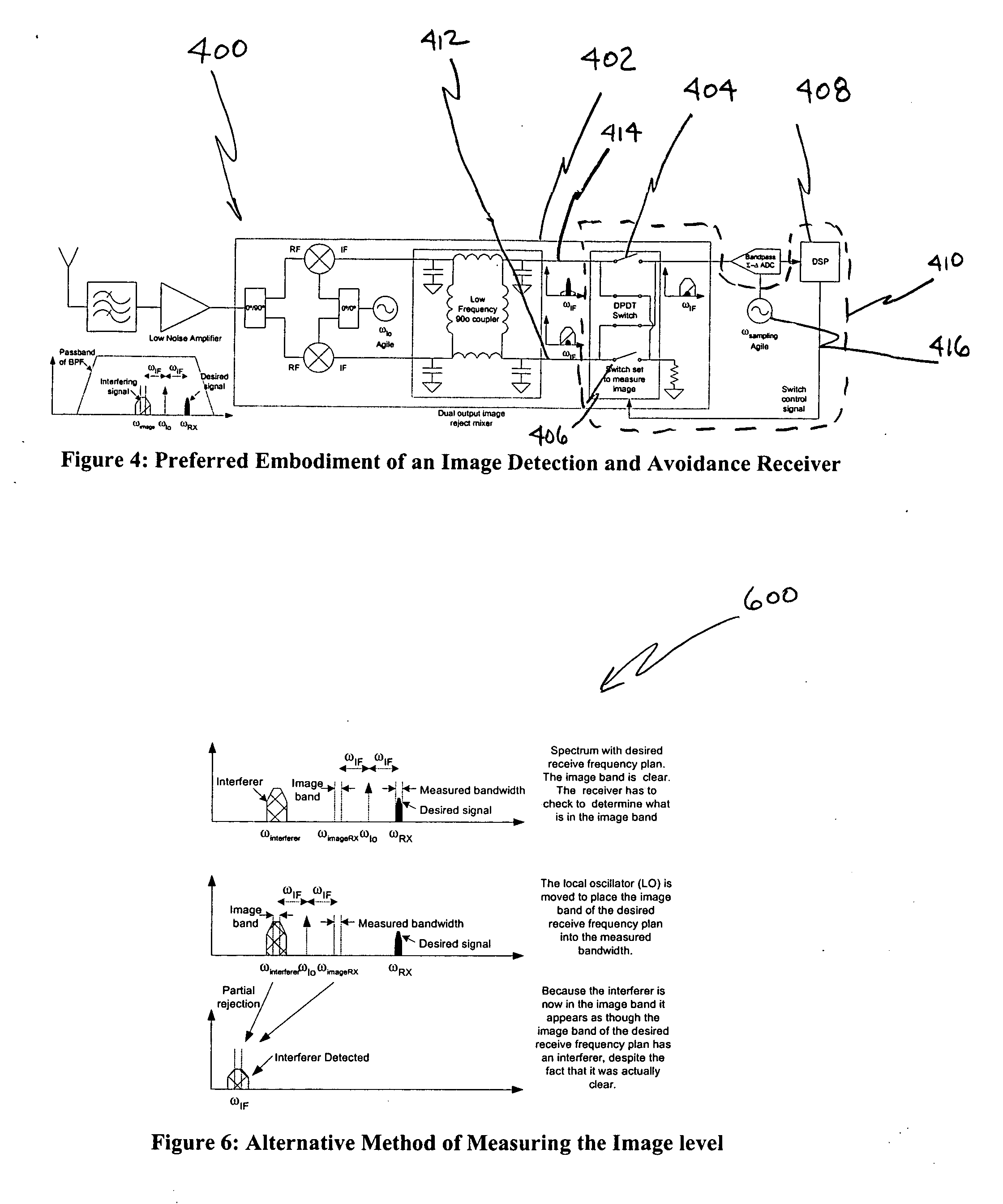
[0028]FIG. 4 illustrates a VLIF image rejection receiver 400 with image detection and avoidance. The VLIF receive 400 includes an image reject mixer 402 with dual outputs, one output 414 for a desired frequency signal and another output 412 for an image frequency signal. A measuring device for measuring power at the dual outputs of the image reject mixer 402 can be implemented using a suggested frequency plan. Immediately prior to a receiver operation, an image detection test would be performed. If a weak power level in the image band was detected, the receiver could proceed with the current frequently plan. If a strong image was detected, the frequency plan would be adjusted, and the image would be measured again. The cycle would continue until a frequency plan with a weak image was identified. An algorithm 500 illustrating how to implement the measuring device for sampling the frequency plan is illustrated in FIG. 5.

[0029] In FIG. 5, the algorithm 500 begins with the step of sele...


PUM


Abstract

A method and apparatus for minimizing image interference using a very low intermediate frequency image rejection receiver is disclosed. Image interference detection and avoidance by frequency plan adjustment within the very low intermediate frequency receiver image rejection receiver minimizes rejection requirements for an image reject mixer. Image rejection can be measured by switching between in-phase and out-of-phase image reject mixer output ports. Rejection may also be measured by creating a tri-mode image reject mixer. A set of linear equations allows rejection to be measured without requiring control of input signals and additional mixers.

Description

CROSS REFERENCE TO RELATED APPLICATION [0001] This application claims priority to co-pending U.S. provisional application entitled, “Very Low Frequency Image Rejection Receiver with Image Interference Detection and Avoidance”, having Ser. No. 60 / 532,568, filed Dec. 29, 2003, which is entirely incorporated herein by reference.FIELD OF THE INVENTION [0002] The present invention is generally related to radio frequency receivers and, more particularly, is related to an apparatus and method for mitigating image interference using a very low intermediate frequency (VLIF) receiver. BACKGROUND OF THE INVENTION [0003] Many conventional radio receivers for use in portable communication devices, such as cellular telephones, are of the super-heterodyne type in which a radio signal to be received is first down-converted to an intermediate frequency (IF), which is still within the radio frequency range, and then further down-converted to a base-band signal having both in-phase and quadrature-phas...

Claims


Application Information

Patent Timeline
Patent Type & Authority Applications(United States)
IPC IPC(8): H04B1/28H04B1/30
CPCH04B1/30H04B1/28
Inventor LAFLEUR, PHIL
Owner 2201028 ONTARIO
Why Eureka
Try Eureka