
System and method for image noise reduction using a minimal error spatiotemporal recursive filter

a spatiotemporal recursive filter and image noise reduction technology, applied in image enhancement, instruments, electric/magnetic computing, etc., can solve the problems of limiting the visibility of anatomical features, quantum image noise, image noise is undesired, etc., and achieve the effect of reducing image nois

Active Publication Date: 2008-01-08
GE MEDICAL SYST GLOBAL TECH CO LLC
View PDF28 Cites 23 Cited by
  • Summary
  • Abstract
  • Description
  • Claims
  • Application Information

AI Technical Summary

Benefits of technology

The system effectively reduces image noise while maintaining spatial detail in static regions and avoiding motion lag in dynamic regions, enhancing image resolution for both static and dynamic areas.

Problems solved by technology

The number of x-ray photons reaching the x-ray detector is finite, which results in quantum image noise.
Image noise is an undesired effect that may limit a visibility of anatomical features or become otherwise distracting or disturbing to a viewer.
Therefore, temporal filtration is an unsatisfactory method of enhancing a moving image because the averaging of frames may produce unwanted motion blur or motion lag.
However, averaging among a neighborhood in a current frame may introduce unwanted spatial artifacts.
However, for static objects in an image, spatial filtration introduces artifacts while temporal filtration does not.
The artifacts consistently degrade an image, making details of the image difficult to view.
Therefore, spatial filtration is an unsatisfactory method of enhancing static objects in a sequence.
As a result, most combinations of spatial and temporal filters introduce some degree of the disadvantages of both the spatial filter and the temporal filter into the image.
The consequence being insufficient resolution of both static and dynamic regions of an image.

Method used


Image

  • System and method for image noise reduction using a minimal error spatiotemporal recursive filter
  • System and method for image noise reduction using a minimal error spatiotemporal recursive filter
  • System and method for image noise reduction using a minimal error spatiotemporal recursive filter

Examples


Embodiment Construction

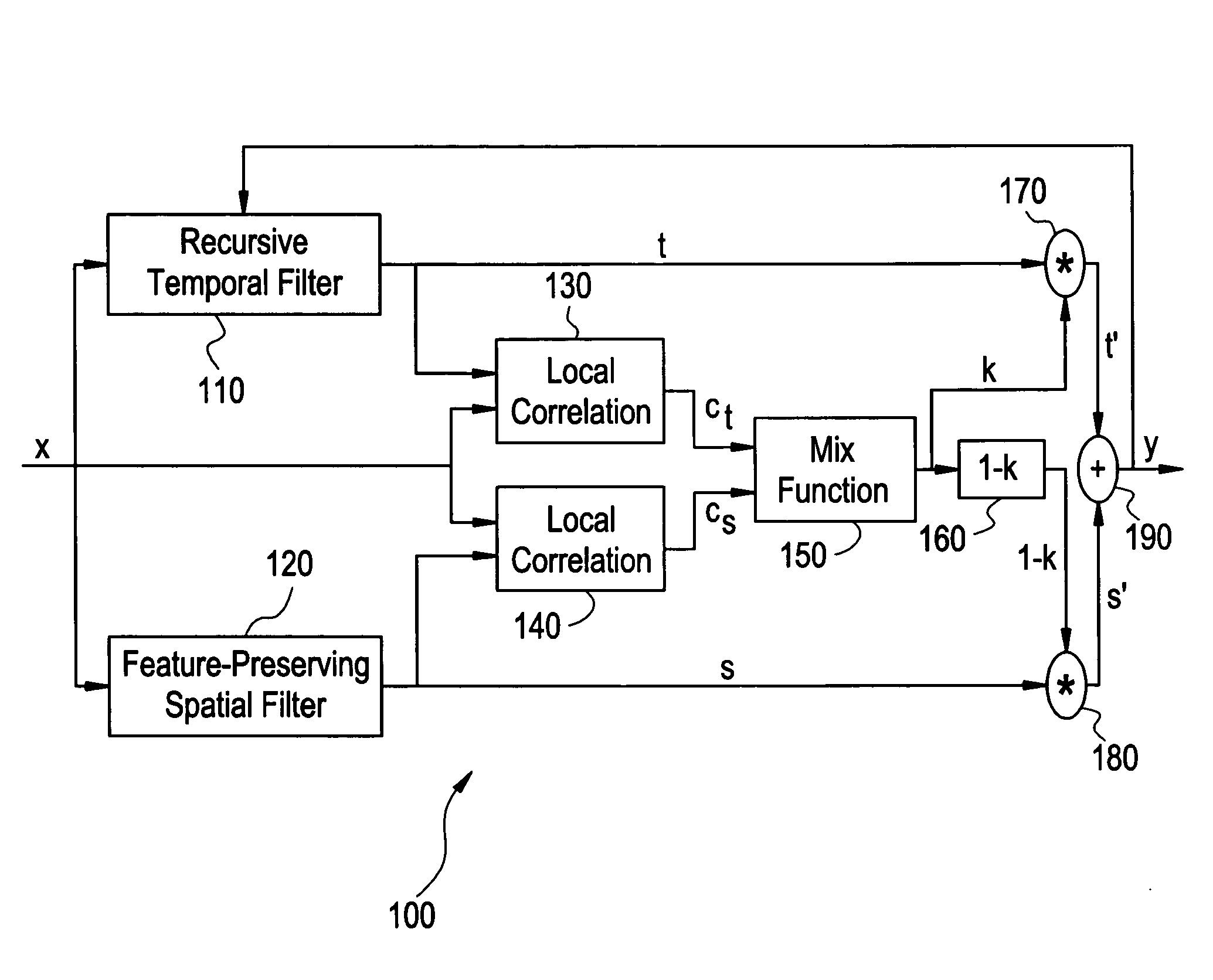
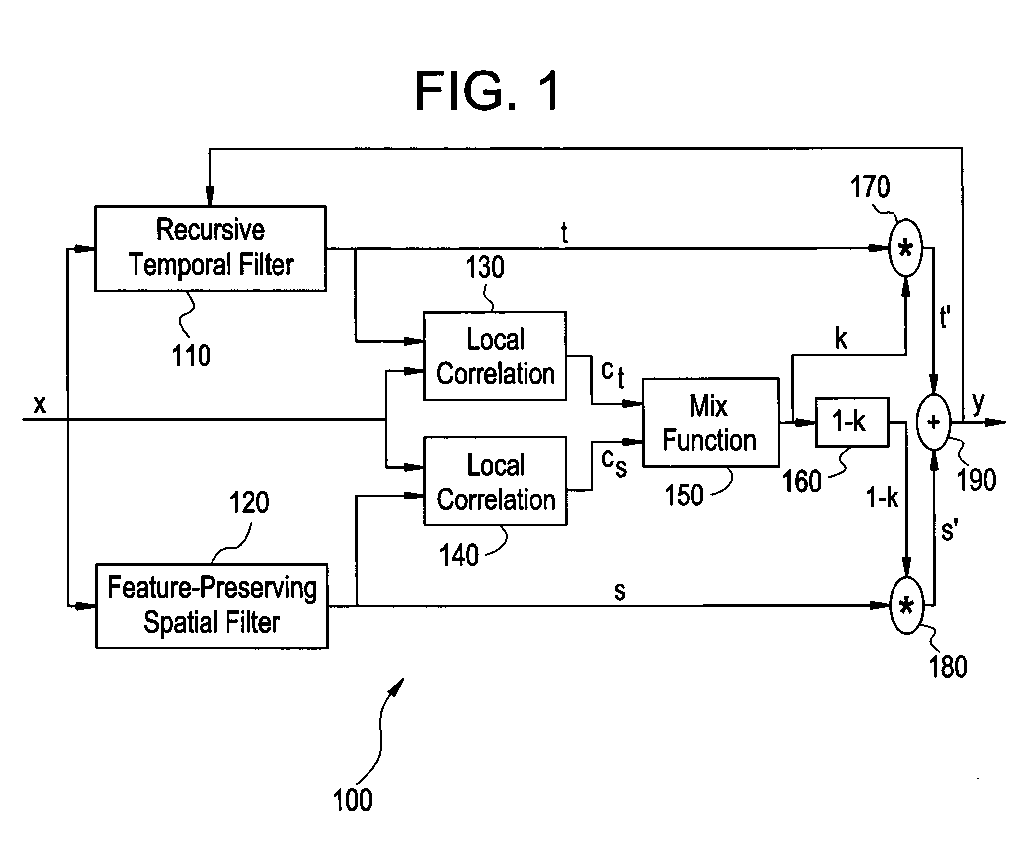
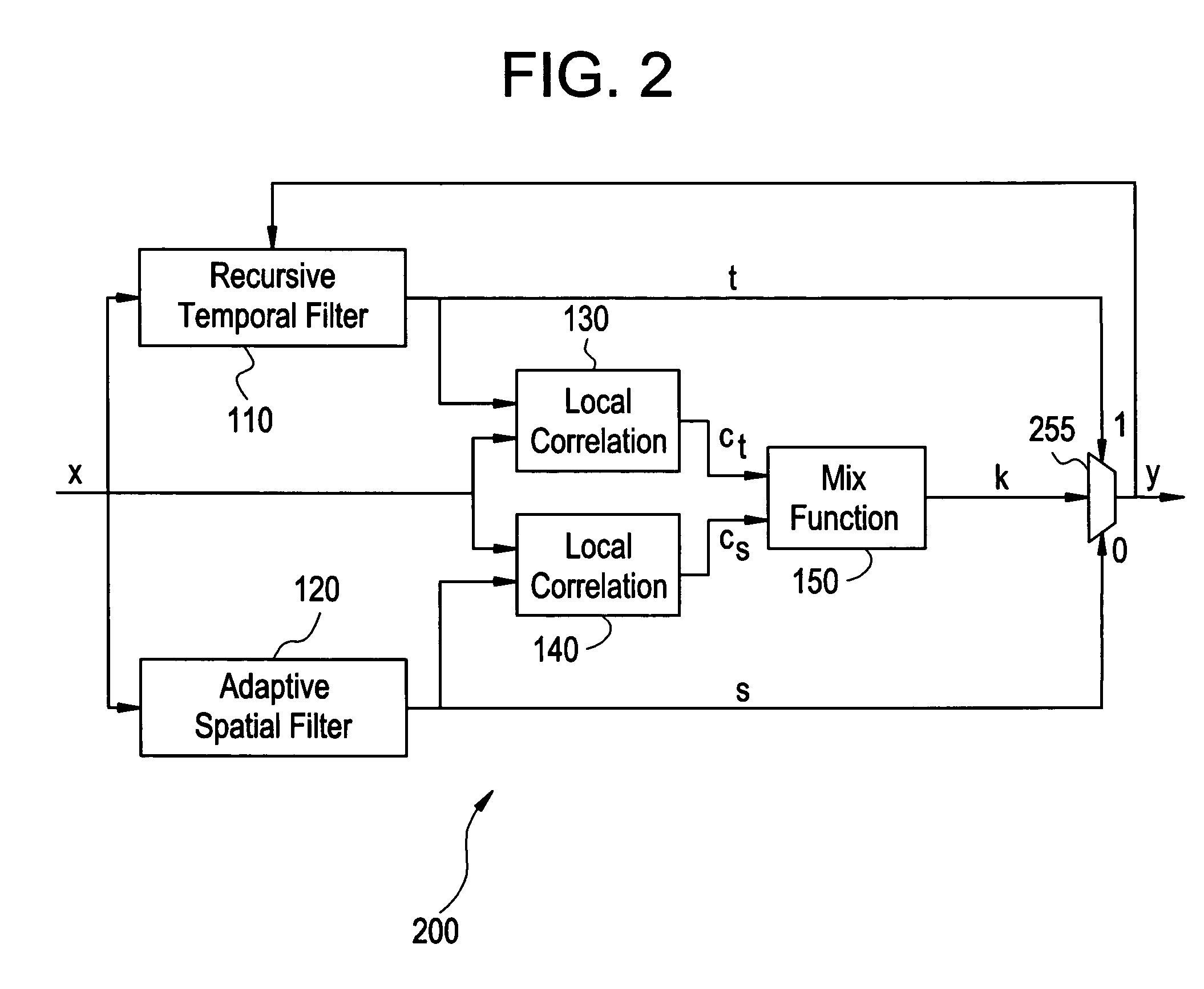
[0024]FIG. 1 illustrates a data flow diagram 100 of a minimal-difference spatiotemporal (MDST) filter used according to an embodiment of the present invention. The data flow diagram 100 represents various units and flow of data in computing an output signal y from an input signal x. The input signal x is input into four units. The input signal x is input into a recursive temporal filter 110, a feature preserving spatial filter 120, a local correlation unit 130, and a local correlation unit 140. The feature preserving spatial filter 120 and the recursive temporal filter 110 produce outputs s and t respectively. The outputs t and s are input into the multiplication units 170 and 180 respectively. The outputs t and s are also input into the local correlation units 130, 140 respectively, together with input signal x. Local correlation units 130, 140 produce outputs ct and cs, respectively. Outputs ct and cs are input into a mix function unit 150. The mix function unit 150 produces an ou...


PUM


Abstract

Certain embodiments of the present invention provide a system and method for reducing image noise with the use of a minimal error spatiotemporal recursive filter. An input image is filtered both temporally and spatially, producing a temporal output and a spatial output. Both the temporal output and the spatial output are correlated with the input image to produce a temporal correlation output and a spatial correlation output. The temporal correlation output and the spatial correlation output are mixed to generate a selecting signal. The selecting signal directly or indirectly determines the composition of an output image. The selecting signal may select a portion of the temporal output and a portion of the spatial output to compose an output image. Alternatively, the selecting signal may select either the temporal output or the spatial output to compose an output image.

Description

BACKGROUND OF THE INVENTION[0001]The present invention generally relates to a system and method for reducing noise in fluoroscopic image processing. In particular, the present invention relates to a system and method for spatiotemporal filtration of fluoroscopic images.[0002]Imaging systems encompass a variety of imaging modalities, such as x-ray systems, computerized tomography (CT) systems, ultrasound systems, electron beam tomography (EBT) systems, magnetic resonance (MR) systems, and the like. Imaging systems generate images of an object, such as a patient, for example, through exposure to an energy source, such as x-rays passing through a patient, for example. The generated images may be used for many purposes. For instance, the images may be used for detecting internal defects in a structure, detecting fluid flow within a structure, or showing the presence or absence of objects in a structure. Additionally, imaging systems may be used for minimally-invasive medical procedures ...

Claims


Application Information

Patent Timeline
Patent Type & Authority Patents(United States)
IPC IPC(8): G06K9/40G06G7/02A61B6/00G06T5/00
CPCG06T5/002G06T5/20G06T5/50G06T2207/10016G06T2207/10121G06T2207/20182G06T2207/20192G06T5/70
Inventor YATSENKO, DIMITRI VICTOROVICHBATES, DANIEL MAHONRI
Owner GE MEDICAL SYST GLOBAL TECH CO LLC
Learn More