Nimble arm of six-DOF robot

A degree of freedom, robot technology, applied in the field of robot arms, can solve the problems of low integration, heavy robot arm, limit the integration of dexterous hands and robot systems, etc., to achieve the effect of high integration, simple structure and light weight

Inactive Publication Date: 2010-06-23
HARBIN INST OF TECH
View PDF0 Cites 33 Cited by
  • Summary
  • Abstract
  • Description
  • Claims
  • Application Information

AI Technical Summary

Problems solved by technology

[0003] The purpose of the present invention is to provide a six-degree-of-freedom robot dexterous arm to solve the problems of existing robot arms with heavy weight and low integration, which limit the integration of dexterous hands and robot systems

Method used


Image

  • Nimble arm of six-DOF robot
  • Nimble arm of six-DOF robot
  • Nimble arm of six-DOF robot

Examples


specific Embodiment approach 1

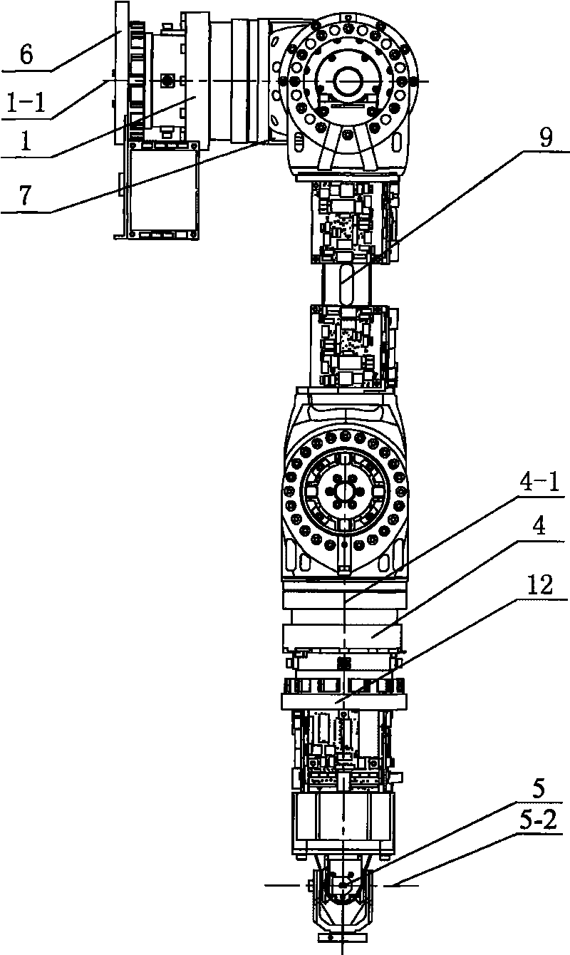
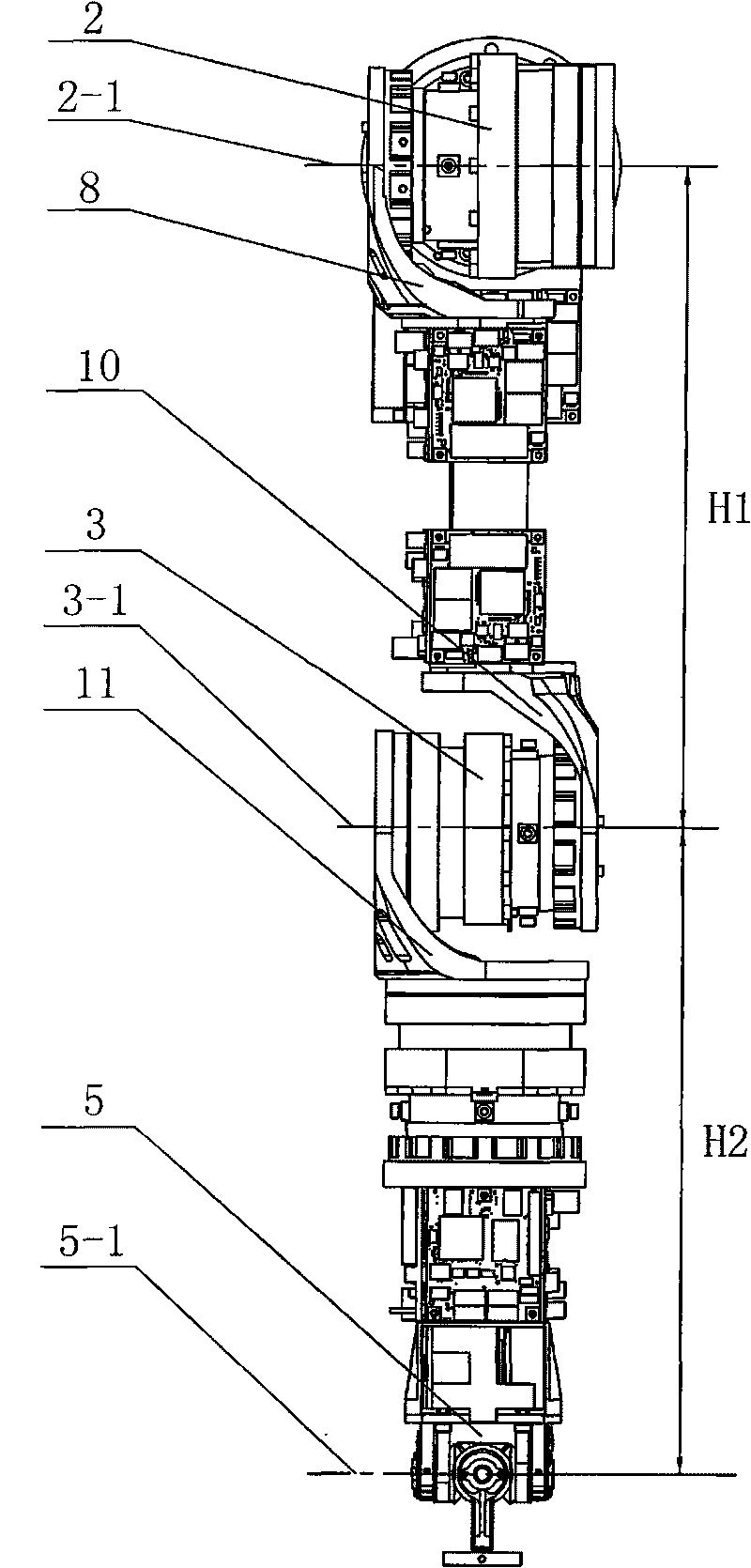
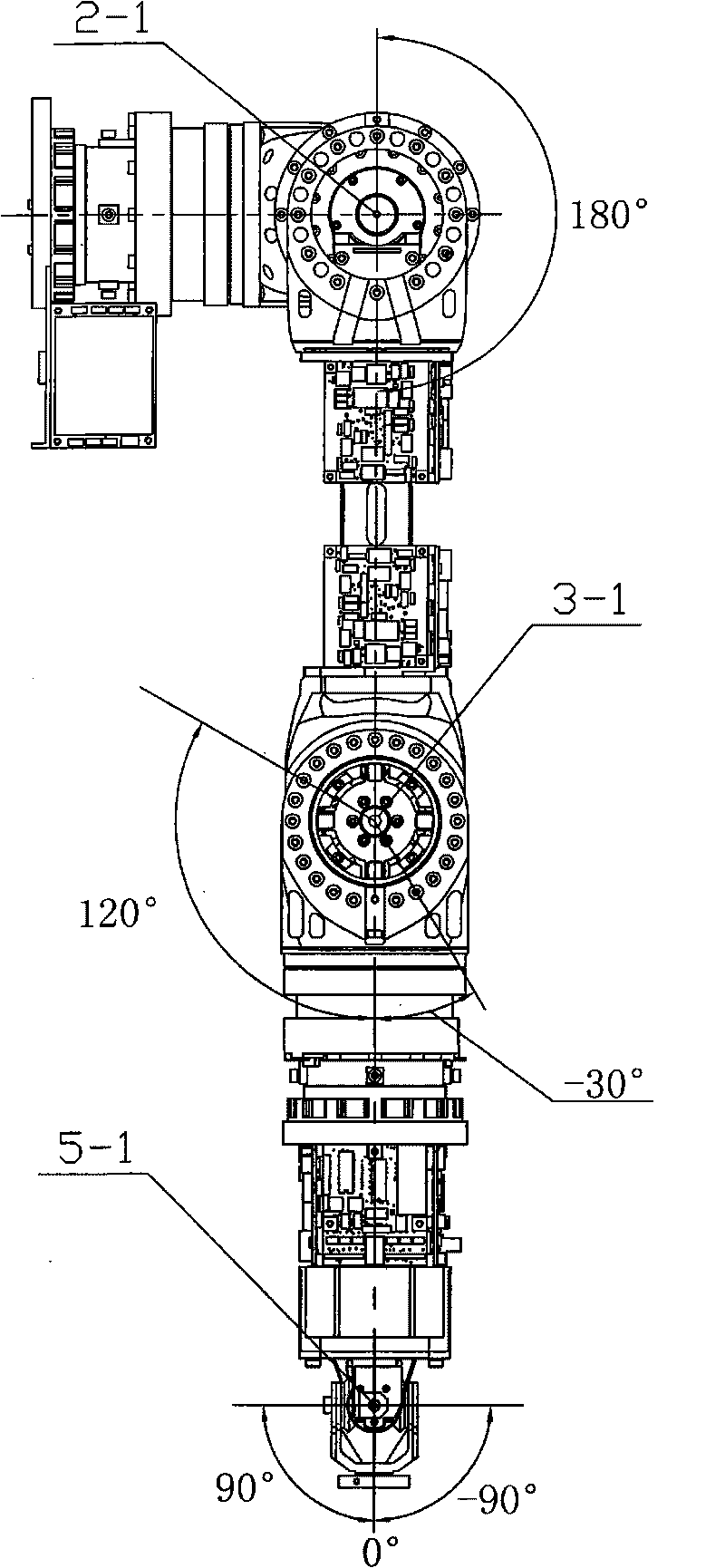
[0007] Specific implementation mode one: combine Figure 1-Figure 14 Describe this embodiment, the arm of this embodiment is composed of first shoulder joint 1, second shoulder joint 2, first elbow joint 3, second elbow joint 4, two-degree-of-freedom wrist joint 5, base 6, first shoulder joint Connecting part 7, second shoulder joint connecting part 8, upper arm 9, first elbow joint connecting part 10, second elbow joint connecting part 11, forearm 12, first shoulder joint circuit board 14-1, second shoulder joint circuit board 14-2, the first elbow joint circuit board 14-3, the second elbow joint circuit board 14-4, the wrist joint circuit board 14-5 and a plurality of wires 15, and the upper arm 9 and the forearm 12 are provided with inner cavities The first fixed end 1-3 of the first shoulder joint 1 is connected to the base 6, and the first output end 1-4 of the first shoulder joint 1 is connected to the second shoulder joint 2 through the first shoulder joint connector 7....

specific Embodiment approach 2

[0008] Specific implementation mode two: combination Figure 10a-Figure 10c Describe this embodiment, the wiring path between the output end of the first shoulder joint circuit board 14-1 of this embodiment and the input end of the second shoulder joint circuit board 14-2 is: the wire 15 goes around the base 6 from The first axial central hole 1-5 of the first shoulder joint 1 passes through and walks around the shoulder joint connector 7, then passes through the second axial central hole 2-5 of the second shoulder joint 2 and walks around the second Shoulder joint connector 8 penetrates into the inner cavity of upper arm 9, passes through the middle position of the side wall of upper arm 9 and is connected to the input end of the second shoulder joint circuit board 14-2; the output of the first elbow joint circuit board 14-3 The routing path between the terminal and the input end of the second elbow joint circuit board 14-4 is: the wire 15 penetrates from the side wall of the...

specific Embodiment approach 3

[0009] Specific implementation mode three: combination figure 1 , figure 2 , Figure 13 with Figure 14Describe this embodiment, the wiring route between the first output end 1-4 of the first shoulder joint 1 of this embodiment and the first electrical system 1-10 of the first shoulder joint 1 is: the wire 15 runs from the first shoulder The first output end 1-4 of the joint 1 is drawn through the first axial center hole 1-5 of the first shoulder joint 1 to be connected with the first electrical system 1-10 of the first shoulder joint 1; The wiring path between the second output end 2-4 and the second electrical system 2-10 of the second shoulder joint 2 is: the wire 15 is drawn from the second output end 2-4 of the second shoulder joint 2 through the second The second axial central hole 2-5 of the shoulder joint 2 is connected with the second electrical system 2-10 of the second shoulder joint 2; the third output end 3-4 of the first elbow joint 3 is connected with the se...


PUM


Abstract

The invention discloses a nimble arm of six-degree of freedom (DOF) robot, relating to a robot arm, so as to solve the problems that the arm of the current robot has large weight and low integration level and the integration between a nimble arm and a robot system is limited. A first shoulder joint, which is connected with a base, is connected with a second shoulder joint through a connecting piece of the first shoulder joint; the second shoulder joint is connected with an upper arm through a connecting piece of the second shoulder joint; the upper arm is connected with a first elbow joint through a connecting piece of the first elbow joint; the first elbow joint is connected with a second elbow joint through a connecting piece of the second elbow joint which is connected with a front arm; the front arm is connected with a two-DOF wrist joint; the circuit board of the first shoulder joint is fixedly mounted on the base; the circuit board of the second shoulder joint and the circuit board of the first elbow joint are fixedly connected with the upper arm, and the circuit board of the second elbow joint and the circuit board of the wrist joint are fixedly mounted on the front arm. Wires are connected with the circuit boards of the first shoulder joint, the second shoulder joint, the first elbow joint, the second elbow joint and the wrist joint in sequence. The nimble arm has light weight, high integration and high reliability.

Description

technical field [0001] The present invention relates to a robot arm. Background technique [0002] The robot arm is an important tool for the robot system to realize large-scale macro operations, and has an important impact on the operation ability and operation level of the robot system. Especially in recent years, the rapid development of service robots and special operation robots has put forward higher requirements for the operation arm. At present, the mature robot arms on the market have problems such as heavy weight and low integration, which limit the integration of dexterous hands and robot systems. Contents of the invention [0003] The purpose of the present invention is to provide a six-degree-of-freedom robot dexterous arm to solve the problems of existing robot arms that are heavy in weight and low in integration, which limit the integration of dexterous hands and robot systems. [0004] The technical scheme that the present invention takes for solving the ...

Claims


Application Information

Patent Timeline
Patent Type & Authority Applications(China)
IPC IPC(8): B25J9/08
Inventor 刘伊威张奇谢宗武赵京东刘宏
Owner HARBIN INST OF TECH
Why Eureka
Try Eureka