Elevator control device

An elevator control device and elevator technology, applied in the field of elevator control devices, can solve the problems of rope swing, hoistway contact or hooking, hooking, etc., to achieve the effect of preventing contact and preventing damage

Inactive Publication Date: 2010-06-23
MITSUBISHI ELECTRIC CORP
View PDF1 Cites 8 Cited by
  • Summary
  • Abstract
  • Description
  • Claims
  • Application Information

AI Technical Summary

Problems solved by technology

[0005] When high-rise buildings suffer from long-period earthquakes and strong winds, since they continue to sway in the horizontal direction with the first-order natural period, the machine rooms for accommodating elevator traction machines and the like on the top of the building are continuously applied with long-period When the natural period of the building is close to the natural period of the rope, the rope resonates and swings greatly, which may cause problems of contact or hooking with the hoistway
[0006] In addition, when the resonance of the elevator rope occurs, there is a possibility that the elevator rope will come into contact with the hoistway, the elevator rope will be caught on equipment such as the floor stop boar

Method used


Image

  • Elevator control device
  • Elevator control device
  • Elevator control device

Examples


Embodiment approach 1

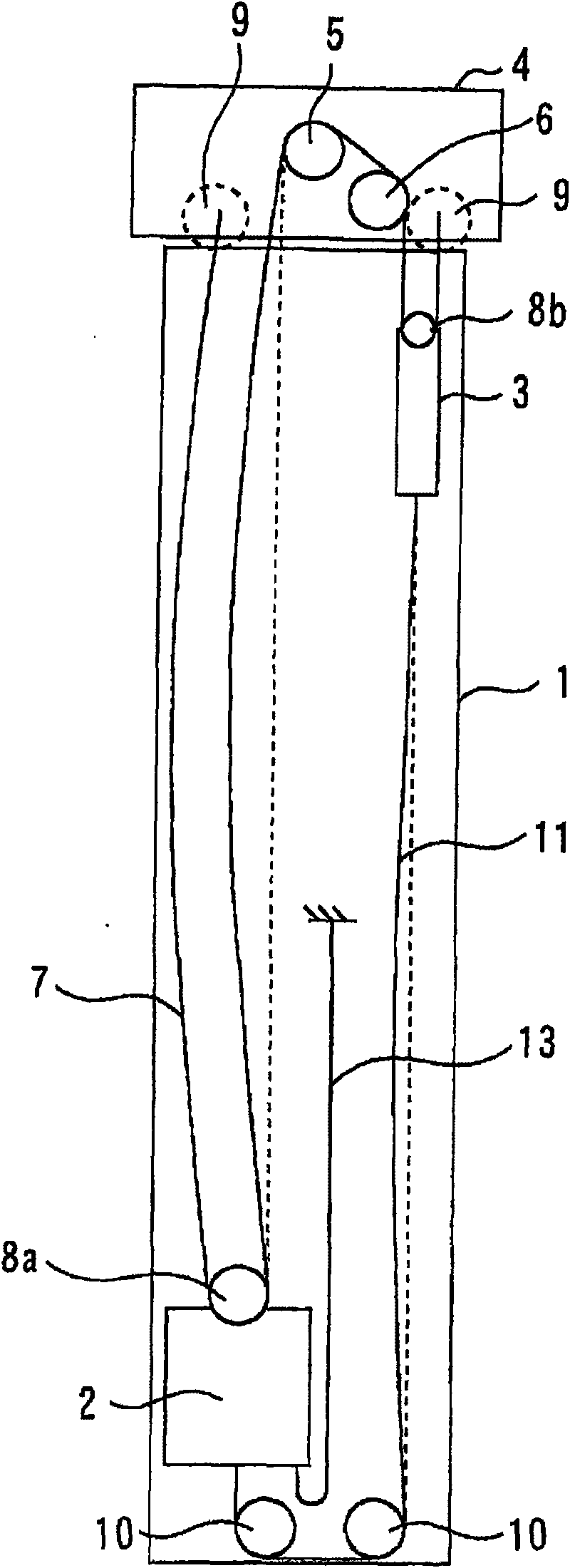
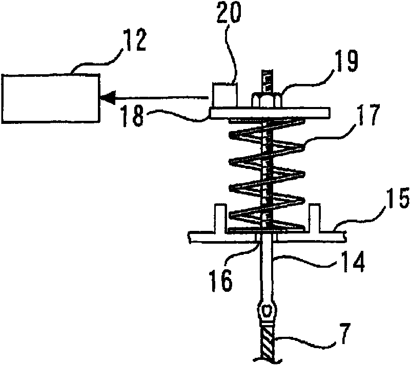
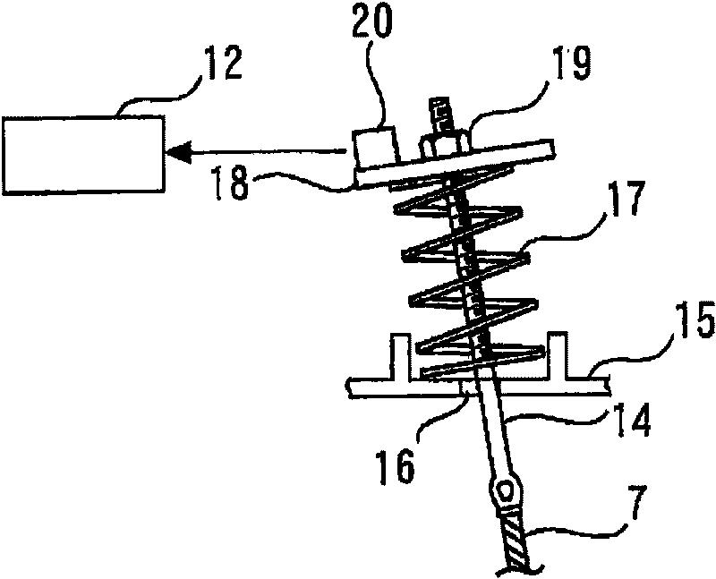
[0024] Figure 1 to Figure 7 Regarding Embodiment 1 of the present invention, figure 1 This is an explanatory diagram showing the state of the rope vibrating due to long-period vibration in an elevator with a 2:1 roping ratio, figure 2 It is a front view showing the normal state of the rope end fixing part (rope end fixing part), image 3 It is a front view showing the rope end fixing part (rope end fixing part) when it is inclined, Figure 4 It is a plan view showing the normal state of the rope end fixing part when a displacement sensor is used for the inclination detection unit, Figure 5 It is a plan view showing the inclination of the rope end fixing part when the inclination detection unit adopts the displacement sensor, Image 6 is a flowchart showing the operation of the first embodiment, Figure 7 This is an explanatory diagram showing how the rope vibrates due to long-period vibration in an elevator with a roping ratio of 1:1.

[0025] In the figure, 1 denotes ...

Embodiment approach 2

[0043] Figure 8 ~ Figure 10 Regarding Embodiment 2 of the present invention, Figure 8 is a front view showing the normal state of the rope end fixing part, Figure 9 It is a front view showing the state when the rope resonance frequency of the rope end fixing part is controlled, Figure 10 It is a flowchart showing the operation of this embodiment. exist Figure 8 with Figure 9 in, with figure 2 with image 3 The same reference numerals denote the same or corresponding parts, and explanations thereof are omitted.

[0044] As mentioned earlier, the natural frequency of the elevator rope is determined according to its length (that is, the position of the car during operation), density and tension, etc. In Embodiment 1, the natural frequency of the elevator rope is controlled by adjusting the position of the car to suppress resonance with the building, but in Embodiment 2 described here, the tension of the elevator rope is controlled by adjusting the tension of the ele...


PUM


Abstract

The invention provides an elevator control device, which can control resonance of elevator cords occurred when long period vibration is generated in a building installed with elevator, and can avoid elevator cords from contacting with the well or hooking on equipments by controlling resonance of elevator cords. The inventive elevator control device is provided with an inclination detecting unit in the elevator installed with cords for ascending and descending the elevator car and the counter-weight, the inclination detecting unit is arranged on the fixed part of the cord end and used for detecting inclination of the fixed part of the cord end.

Description

technical field [0001] The present invention relates to elevator controls. Background technique [0002] As for the conventional elevator control device for suppressing the sway of the elevator rope, the following structure is known: the car frame of the car is suspended on one end side of the rope wound on the traction machine, and the other end side of the rope is suspended. Focusing on the counterweight, this elevator is equipped with a sway suppression device for suppressing the lateral sway vibration of the rope, which is inserted through the rope and fixed to the car frame (for example, refer to Patent Document 1). [0003] [Patent Document 1] Japanese Patent Laid-Open No. 2006-193256 [0004] It is known that the first-order natural period of a high-rise building whose height (H) exceeds 60 m varies with the structure of the building, but is approximately (H[m] / 1[m])×0.025[sec] ( For example, if the building height (H) is 100m, the first-order natural period is abou...

Claims


Application Information

Patent Timeline
IPC IPC(8): B66B5/00B66B1/00
Inventor 佐久间洋一
Owner MITSUBISHI ELECTRIC CORP
Why Eureka
Try Eureka