Reversing radar system

A reversing radar and ultrasonic technology, which is applied in the field of reversing radar system, can solve the problems of reversing radar system error users, etc., and achieve the effect of simple installation and convenient use

Inactive Publication Date: 2010-06-23
LIANCHUANG AUTOMOBILE ELECTRONICS
View PDF0 Cites 16 Cited by
  • Summary
  • Abstract
  • Description
  • Claims
  • Application Information

AI Technical Summary

Problems solved by technology

The error of the reversing radar system is li

Method used


Image

  • Reversing radar system
  • Reversing radar system
  • Reversing radar system

Examples


Embodiment Construction

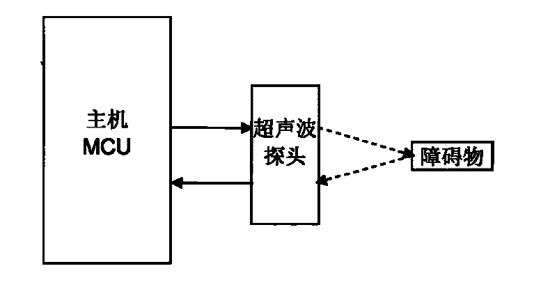
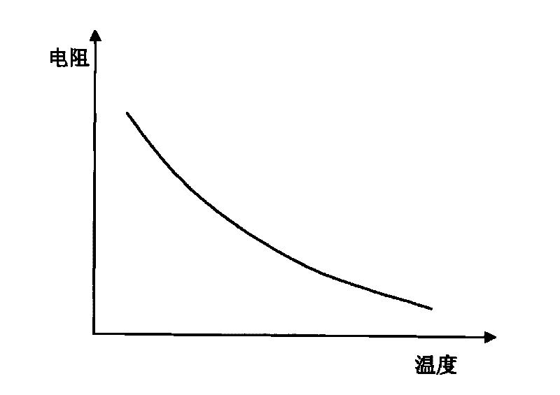
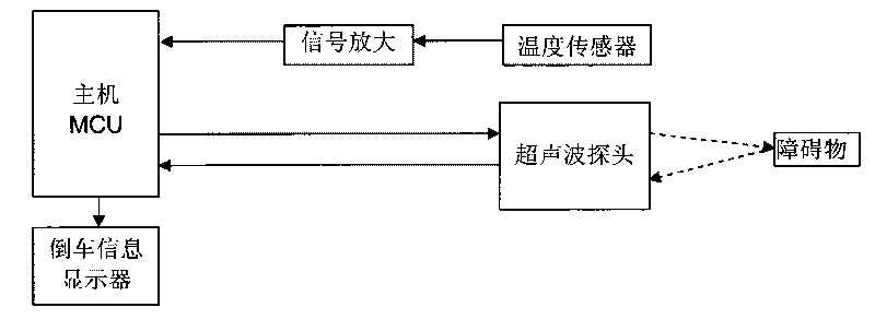
[0012] An embodiment of the reversing radar system of the present invention is as follows: figure 2 As shown, it includes a microcontroller (MCU), an ultrasonic probe, and also includes a temperature sensor and a reversing information display; the microcontroller (MCU) sends a driving signal to the ultrasonic probe, drives the ultrasonic probe to send an ultrasonic signal, and after the driving signal is sent, The microcontroller (MCU) waits for the return signal. After the ultrasonic probe receives the ultrasonic echo signal reflected by the obstacle, the echo signal is amplified and shaped, and then sent to the microcontroller (MCU); the temperature sensor has a resistance that changes with temperature. It is installed near the probe. The temperature sensor here can use NTC (negative temperature coefficient) thermistor, and its resistance value changes with temperature. figure 2 As shown, the material of the NTC thermistor is ceramic (metal oxide), which has the characteri...


PUM


Abstract

The invention discloses a reversing radar system which comprises a microcontroller, an ultrasonic probe and a temperature sensor. The temperature sensor is used for monitoring exterior temperature and sending the exterior temperature to the microcontroller. The temperature sensor has the characteristics that the temperature sensor changes along with the change of temperature. The characteristic change of the temperature sensor at different temperatures and the calibration compensating values of the ultrasonic speed change are stored in a memory. According to the time difference of ultrasonic signal sending and ultrasonic return signal receiving, the exterior temperature sent from the temperature sensor, and the characteristic change of the temperature sensor at different temperatures and calibration compensating values of the ultrasonic speed change stored in the memory, the microcontroller computes the distance from the obstacle. The invention has high precision of detection distance.

Description

technical field [0001] The invention relates to the technical field of automotive electronics, in particular to a reversing radar system. Background technique [0002] Common reversing radar systems such as figure 1 As shown, it includes a microcontroller (MCU) and an ultrasonic probe. When the microcontroller (MCU) is powered on, the microcontroller (MCU) sends a driving signal to the ultrasonic probe, drives the ultrasonic probe to send an ultrasonic signal, and the driving signal is sent. Finally, the microcontroller (MCU) waits for the return signal. After the ultrasonic probe receives the ultrasonic echo signal reflected by the obstacle, the echo signal is amplified and shaped, and then sent to the microcontroller (MCU). ) Calculate the obstacle distance according to the time difference between signal sending and receiving, and output an alarm signal. [0003] The ultrasonic speed is easily affected by the temperature change of the environment. The ultrasonic probe pa...

Claims


Application Information

Patent Timeline
IPC IPC(8): G01S15/08G01S15/93
Inventor 张宣彪罗来军单津晖郭凤龙
Owner LIANCHUANG AUTOMOBILE ELECTRONICS
Why Eureka
Try Eureka