Nasal Ventilation Cannula System and Methods

a technology of nasal ventilation and cannula, which is applied in the field of nasal ventilation cannula system and methods, can solve the problems that the nasal ventilation cannula does not enhance ventilation, and achieve the effects of reducing the comfort of the gas flow, preventing the occlusion of the tube, and lessening the pressure generation

Inactive Publication Date: 2013-04-18
WONDKA ANTHONY DAVID
View PDF11 Cites 36 Cited by
  • Summary
  • Abstract
  • Description
  • Claims
  • Application Information

AI Technical Summary

Benefits of technology

[0064]FIG. 4 shows a front view cross-section through the nose and ventilation cannula of the system shown in FIG. 3, showing the sensing tubes 14 pinching the nostril septum 2, the gas delivery nozzles 12 just lateral to the sensing tubes, and an interconnecting manifold 22 setting the distance between the sensing tubes. In the prior art described in US Patent Application No. 20110094518 the jet nozzles are positioned to the medial side of the sensing tubes, which positions the nozzles at an arbitrary location relative to the nostril anatomy, and in that particular case potentially too close to the nostril wall. An advantage of the present invention over the prior art is that the gas delivery nozzles are consistently positioned at an ideal location relative to the nostril's anatomical features, regardless of the patient's anatomy. Multiple sizes with different nozzle-to-nozzle spacings, or different sensing tube-to-sensing tube spacings, or with a spacing adjustment with a connector 23 are incorporated into the design to assure that the delivery nozzles are positioned at the ideal location. As can be seen in FIG. 4 the sensing tubes 14 position the ventilation gas flow 36 substantially in the center area of the nostril.
[0065]FIG. 5 describes a top view of the distal end of the nasal cannula in a user's nose, for example at the sectional view indicated by line C-C in FIG. 3. As can be seen, the sensing tubes 14 locate the tip of the gas delivery nozzles 12 lateral to the sensing tubes, and optionally slightly anteriorly. This position positively locates the gas delivery nozzle tips away from the wall of the nostrils N, and substantially centered in the nostril opening, so that the pressure profile exiting the gas flow nozzles 26 is centered or semi-centered with the nostril foramen. If the gas delivery nozzles are not centered, the gas flow unevenly impinges on a wall of the nostril which lessens the pressure generation and decreases the comfort of the gas flow. A chamfer 32 may be provided in the sensing tube 14 distal end to provide clearance to the gas exiting the nozzle openings 26. Optionally, the gas delivery nozzle openings 26 cross-sectional shape may be matched to match the relief or chamfer 32 in the sensing tube.
[0066]FIG. 6 describes a partial hidden line front view of an alternate ventilation cannula configuration in which the gas delivery nozzle 12 tips are located proximally to the entrance to the nostril, at a distance between 0 mm and 20 mm. Ideally, the distance d from the gas delivery nozzle to the entrance to the nostril is equal to one-half to three-fourth's the effective inside diameter of the nostril entrance during inspiration, or 8-10 mm for adults, 4-6 mm for pediatrics and 2-4 mm for infants. The interconnecting manifold 22 top surface is fit against the septum of the nostril to help position the sensing tubes and the gas delivery nozzles in their proper distance relative to the plane of the entrance to the nostrils to achieve the distances described above. The gas delivery nozzles tips are aligned to direct the gas exiting the nozzles along the centerline of the nostril foramen. The sensing tubes may be self-adjusting to the anatomy of the patient due to the compliance of the material, typically plastisol or silicone. The gas delivery nozzles resist deformation of their angular alignment with the nostril foramen, due to the semi-rigidity of their material, typically PVC or semi-rigid silicone. Alternately the ventilation cannula is provided in different sizes with an accompanying sizing guide so that the user can select a size that properly fits their nose.
[0067]FIG. 7 describes a closer view of the distal end of the ventilation cannula shown in FIG. 6. The nozzle opening 26 of the gas delivery nozzle is proximal or inferior to the superior or superior surface of the interconnecting manifold 22, therefore setting the dimensional relationship d′ between the gas delivery nozzle and the entrance to the nozzle. In order for the sensing tubes to not interfere with the gas flow exiting the gas delivery nozzle, the sensing tubes are chamfered 32 so that they are not in the gas delivery pathway, as will be described in more detail later. It is important that the sensing tubes hug the inside wall of the nostril, in order to assure that the gas delivery nozzle is properly positioned. Optionally, the interconnecting manifold can be removably attachable from the left and right cannula distal ends, so that the space between the left and right sensing tubes can be adjusted to fit the nose of an individual patient. Optionally, multiple sizes are made available for each patient group in order to meet the size requirements.
[0068]FIG. 8 describes a front sectional view through the nose of the distal end of the ventilation cannula, during expiratory phase of breathing. The patient's breath 44 is exhaling freely around the cannula. During expiratory phase, a purge flow of gas 40 can exit the sensing tubes to prevent occlusion of the tube with breathing fluids. The purge flow can be air or oxygen gas 42. Optionally the sensing tubes can be used to supply the oxygen gas required for maintaining the patient's oxygen saturation, and can be delivered continuously or intermittently. If continuous, the flow amplitude can increase during inspiratory phase and decrease during expiratory phase, or can be of constant amplitude. If intermittent, the gas can be delivered during inspiratory phase and switched off during expiratory phase. If PEEP is desired, gas can be delivered during expiratory phase. In FIG. 8 a diameter reduction in the gas delivery nozzle tip is shown to create the jet effect, and the sensing tube distal end is chamfered or angled to make clearance for the gas exiting the gas delivery nozzle.
[0069]FIG. 9 describes the view shown in FIG. 8 during inspiratory phase. A pressure head + is developed in the nostril at a distance inside the nostril. A negative pressure zone − is created outside of the pressure head, which entrains ambient air 38 into the nostril N to join with the gas delivered by the cannula, and the patient's spontaneously inspired ambient air (not depicted). A purge flow 40, 42 can be delivered through the breath sensing channel 34. The positive pressure zone of the gas delivery intersects with the wall of the nostril at a location inside the nose, typically 2 mm-10 mm inside from the opening, preferably 4-6 mm inside for adults, 3-4 mm for pediatrics, and 1-2 mm for infants. The jet gas delivery entrains ambient air as shown, typically 50-150% of the volume being supplied by the jets. For the adult sizes, the flow exiting the gas delivery nozzles is approximately 15 lpm for typically 0.75-1.0 second long bursts, and the entrained ambient airflow is 10-30 lpm depending on the prevailing conditions. Optionally, the gas being delivered by the gas delivery nozzles can be air to provide the mechanical breathing support, while oxygen gas is delivered through the sensing tubes for oxygenation.

Problems solved by technology

Nasal cannulae used for supplemental oxygen delivery are common and accepted among users and the general public, however, a nasal cannula does not enhance ventilation due to its lack of delivery power.
In contrast, nasal mask ventilation enhances ventilation by delivering the gas under power, but these systems are undesirable to users because of their obtrusiveness, and they are generally ostracized by the general public.

Method used


Image

  • Nasal Ventilation Cannula System and Methods
  • Nasal Ventilation Cannula System and Methods
  • Nasal Ventilation Cannula System and Methods

Examples


Embodiment Construction

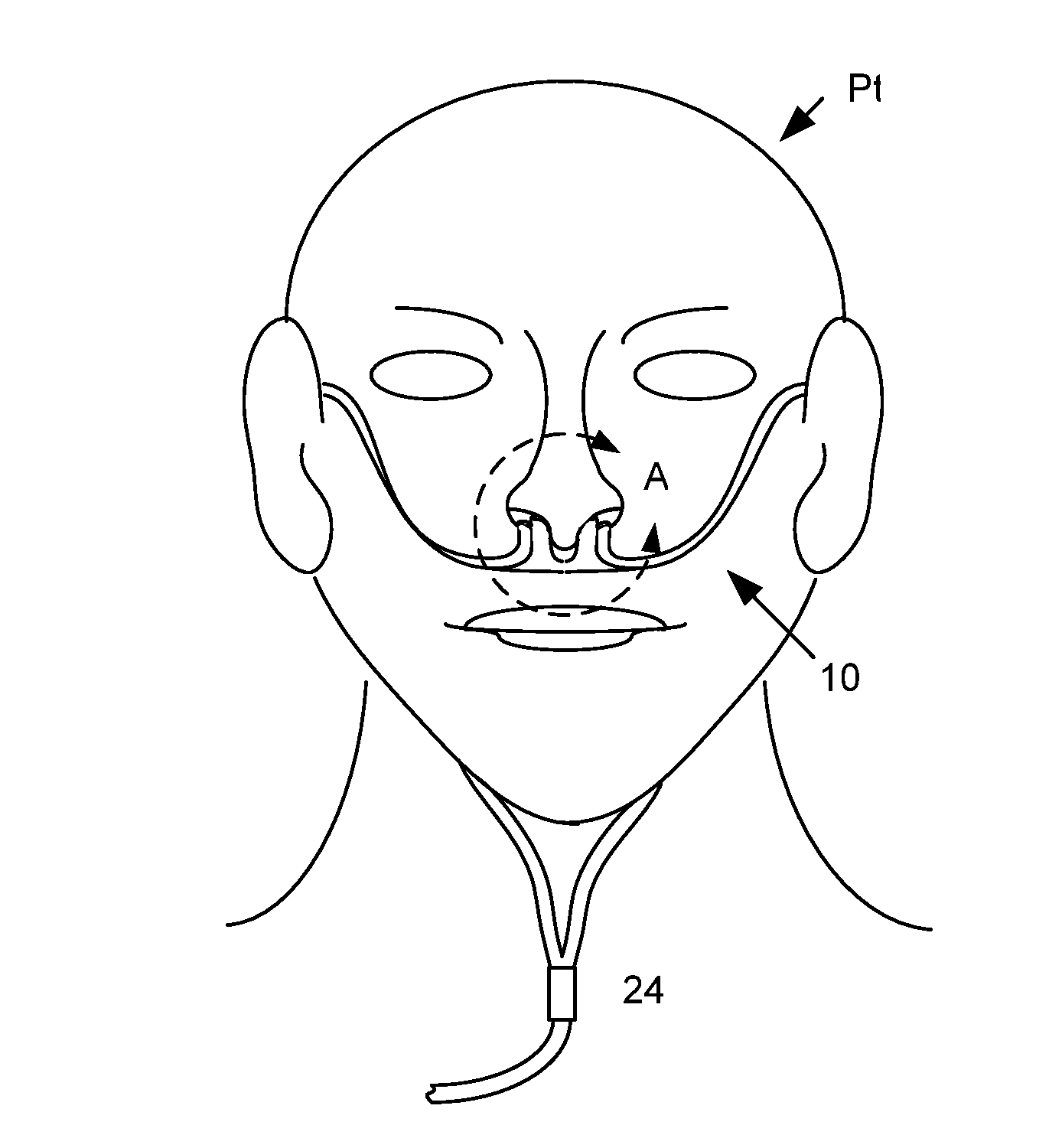
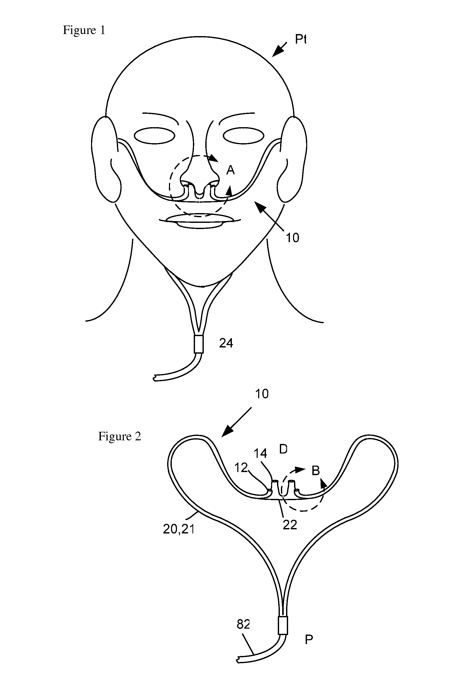
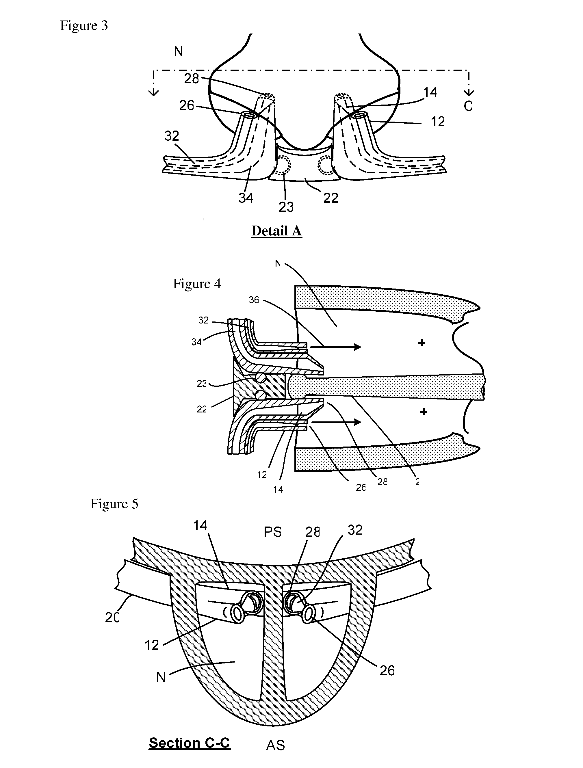
[0063]FIG. 1 describes the nasal ventilation cannula 10 being worn by a user Pt, and a Y connection 24. FIG. 2 shows an isometric view of the nasal ventilation cannula assembly 10 with gas delivery tubing 20 and breath sensing tubing 21 and interconnecting manifold 22, with a proximal end P with gas delivery circuit 82 which connects to a gas flow source and a distal end D which delivers gas flow to a patient's nasal airway via a ventilation gas delivery nozzle 12. User breathing is sensed via a sensing tube 14. FIG. 3 describes a detailed partial hidden live view of the distal end of the ventilation cannula 10 at detail A of FIG. 1. The gas delivery tube and breath sensing tubes are shown, as well as an interconnecting manifold 22 connected to the left and right sides. The interconnecting manifold can be adjustable or removable for example with connectors 23 in order to set the distance between the sensing tubes so that the sensing tubes hug the medial wall of the nostril N. The br...


PUM


Abstract

A nasal cannula ventilation system is described for treating lung disease or for exercise conditioning, incorporating a Venturi system. The ventilation cannula comprises unique positioning features to positively locate a gas delivery nozzle in an optimal location to optimize Venturi performance, patient comfort and fitment to the patient. The cannula is low profile, making it as realistic to wear and use as a standard oxygen cannula, and is simple rending the cost reasonable. The ventilation cannula uses a simple low cost ventilator as a gas delivery control system which is compatible with existing gas sources. The system is used (1) during stationary use to unrest the respiratory muscles to increase tolerance to activity after a treatment session, or (2) to enable activity within a distance from a stationary gas source, (3) during ambulatory use using a portable gas source to enable mobility, and (4) for enhanced fitness conditioning.

Description

PRIORITY CLAIM[0001]This application claims priority to U.S. Provisional Patent Application No. 61 / 539,228 filed on Sep. 26, 2011.FIELD OF THE INVENTION[0002]The present invention relates to the field of improving ventilation to improve exercise capacity in fitness training, and or to increase exertion tolerance in the treatment of lung disease such as chronic obstructive pulmonary disease (COPD), interstitial lung disease (ILD) and other respiratory disorders. More specifically, this invention involves delivering supplemental oxygen to a person under enough pressure to decrease the work of breathing and or to increase exercise capacity. The invention employees a nasal ventilation cannula with a unique minimally encumbering system that delivers the oxygen with a Venturi effect to improve the efficiency of respiration and ventilation.BACKGROUND OF THE INVENTION[0003]Regarding fitness training, increasing exercise capacity using supplemental aides to obtain a competitive advantage is ...

Claims


Application Information

Patent Timeline
Patent Type & Authority Applications(United States)
IPC IPC(8): A61M15/08A61M16/00
CPCA61M15/08A61M16/204A61M16/12A61M2016/0021A61M2016/0027A61M2202/0208A61M2205/3393A61M2205/42A61M2205/502A61M2205/8206A61M2209/084A61M2230/432A61M16/0677A61M16/101A61M16/0057A61M16/0063A61M16/0833A61M16/0841A61M16/085
Inventor WONDKA, ANTHONY D.
Owner WONDKA ANTHONY DAVID
Why Eureka
Try Eureka