

Method and system for expanding capacity of memory device
A storage device and expansion method technology, applied in the field of data storage, can solve the problems of insufficient utilization of network bandwidth, inability to re-share network storage devices, and low operating efficiency, and achieve high utilization rate, less network data exchange, and use of Maintenance-friendly effect
- Summary
- Abstract
- Description
- Claims
- Application Information
AI Technical Summary
Problems solved by technology
Method used
Image

Examples
Embodiment Construction
[0071] In order to facilitate a further understanding of the invention, the specific implementation manners of the invention will be described in detail below in conjunction with the accompanying drawings.
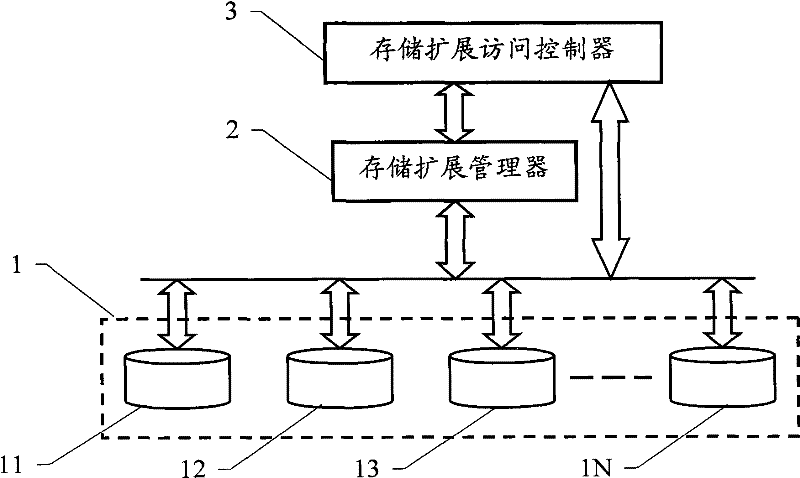
[0072] exist figure 1 In the provided structure, a plurality of storage devices 11, 12, 13...1N constituting the storage device group 1 respectively establish connections with the storage expansion manager 2 and the storage expansion access controller 3 at the same time. Devices 11, 12, 13...1N include local storage devices and network storage devices. Each storage device constituting the storage device group 1 is used to store data, and is expanded and managed by the storage expansion manager 2 , and its I / O access is realized under the control of the storage expansion access controller 3 .
[0073] Described local storage device is the memory directly connected locally, including hard disk, electronic hard disk, Flash memory disk, optical storage device, floppy disk dri...
PUM
 Abstract
Description
Claims
Application Information