RJ45 joint device with key structure to change pin definition

A technology of RJ45 and connector device, which is applied to the parts, coupling devices, connection and other directions of the connection device, which can solve the problem of easily occupying the available space of the electronic device, and achieve the effect of saving the available space.

Active Publication Date: 2010-06-23
MOXA INC
View PDF0 Cites 4 Cited by
  • Summary
  • Abstract
  • Description
  • Claims
  • Application Information

AI Technical Summary

Problems solved by technology

[0006] In view of the problem in the prior art that the use of various connector devices easily occupies the available space of the electronic device, the present invention provides an RJ45 connector device with a button structure to change the pin position definition, wherein:

Method used


Image

  • RJ45 joint device with key structure to change pin definition
  • RJ45 joint device with key structure to change pin definition
  • RJ45 joint device with key structure to change pin definition

Examples


Embodiment Construction

[0052] The implementation of the present invention will be described in detail below with reference to the drawings and examples, so as to fully understand and implement the implementation process of how to use technical means to solve technical problems and achieve technical effects in the present invention.

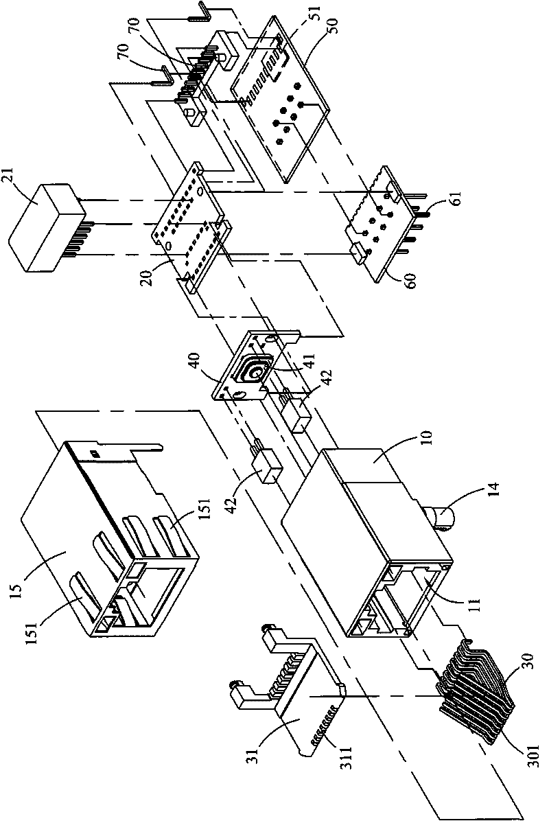
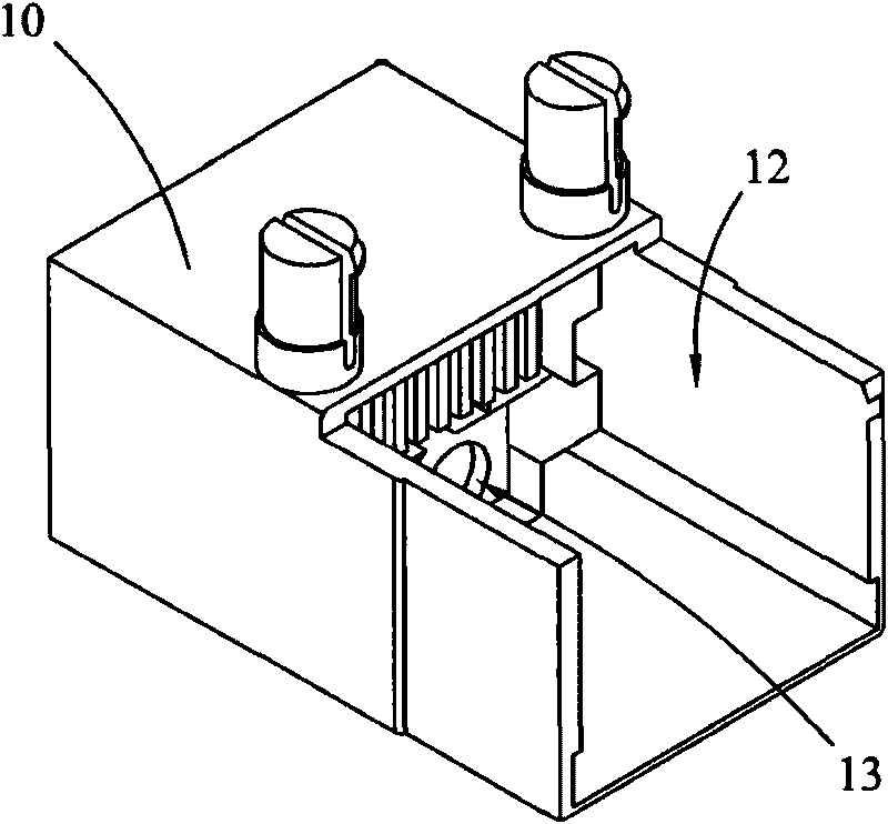
[0053] The following will illustrate the RJ45 connector device with key structure of the present invention to change the definition of the pin position, and please refer to figure 1 as shown, figure 1 Illustrated is the three-dimensional exploded view of the RJ45 connector device with a button structure to change the pin position definition of the present invention; and please cooperate figure 2 Be explained, figure 2 It is a perspective view of the base of the RJ45 connector device according to the present invention which has a button structure to change the definition of the pin position.

[0054] The RJ45 connector device provided by the present invention has a b...


PUM


Abstract

The invention provides an RJ45 joint device with a key structure to change pin definition. A conversion processor, a key, an information processor and an output pin are arranged on the RJ45 joint device. When the key is pressed to trigger a conversion signal, the conversion processor first converts one part of input information into relay information, and the information processor can convert the input information and the relay information into output information through specified processing according to the conversion signal and then output the output information by the output pin. By adopting the above technical scheme, the RJ45 joint device can solve the problem that various joint devices can easily occupy available space of an electronic device, thereby achieving the technical effects of saving the available space of the electronic device and leading the single joint device to have the function of switching the pin definition.

Description

technical field [0001] A connector device, in particular an RJ45 connector device with a button structure to change the definition of pin positions. Background technique [0002] With the rapid progress and development of science and technology, more and more products in the surrounding environment of our life have progressed from traditional mechanical simulation to electronic digital control. Therefore, the connection between various electronic products or the connection between electronic components All must rely on various connectors or joint devices to achieve the purpose of electrical connection. The more common connectors include ring connectors, specification conversion connectors and other connectors, and the more common joint devices There are various connector devices such as RJ45 connector device and USB connector device. [0003] Corresponding to each connector or joint device of different specifications, the data read or received by the pins of its electrical ...

Claims


Application Information

Patent Timeline
Patent Type & Authority Applications(China)
IPC IPC(8): H01R13/66H01R13/70H01R13/717H04L12/00G06F13/00
Inventor 黄文钦
Owner MOXA INC
Why Eureka
Try Eureka