Charging circuit, medical facility and charging method
A technology of medical equipment and charging circuit, which is applied in the field of charging circuit of medical equipment, can solve the problems of slow system charging speed, fan noise, difficult to support working time, etc., and achieve the effect of ensuring service life and meeting the requirements of charging time
- Summary
- Abstract
- Description
- Claims
- Application Information
AI Technical Summary
Problems solved by technology
Method used
Image
Examples
Embodiment 1
[0031] Please refer to figure 1 , directly control the charging unit through the control unit, and change the magnitude of the charging current, which belongs to open-loop control. Such as manually arbitrarily setting the size of the charging current. The charging unit adjusts the charging current according to the set value.
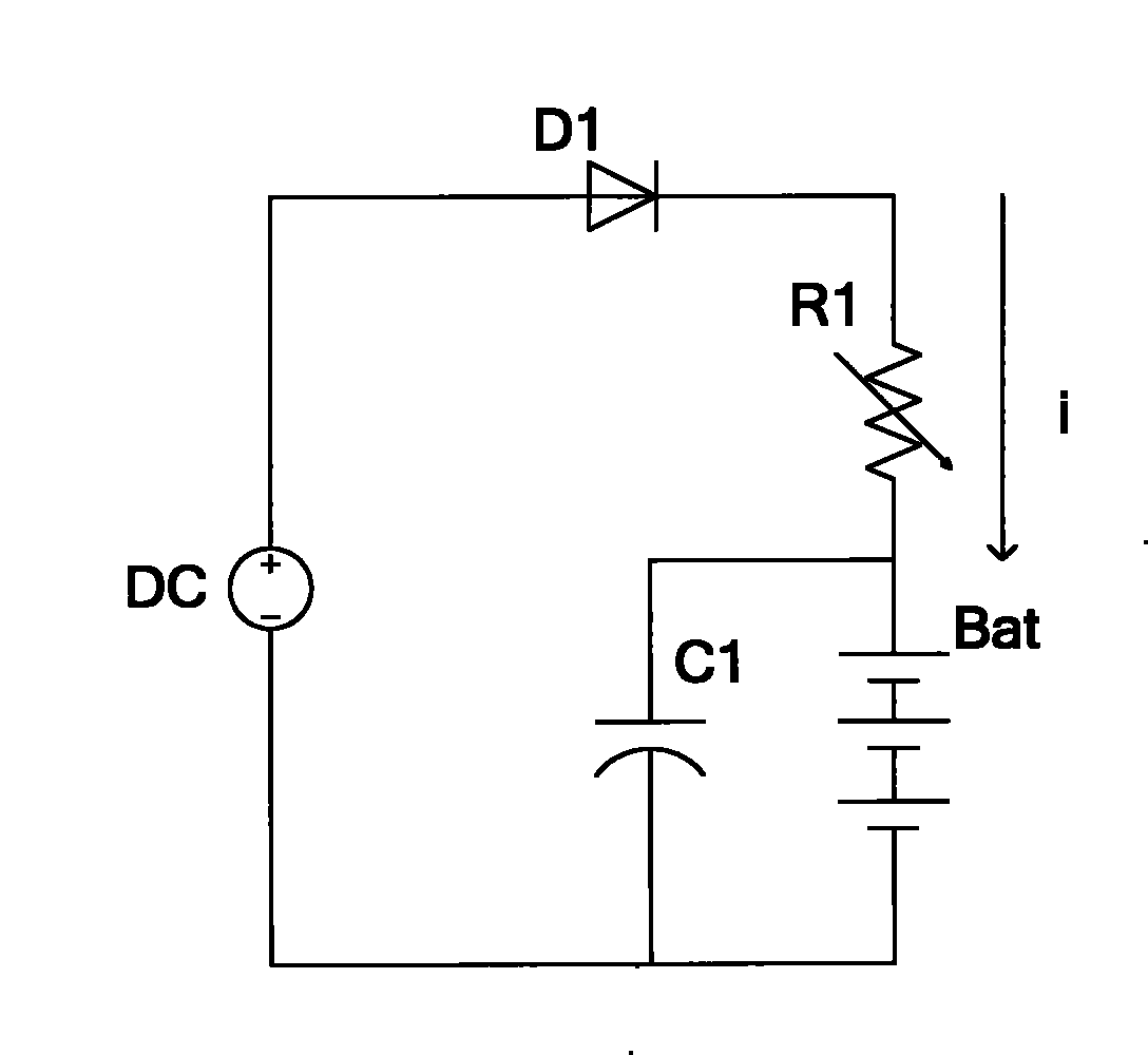
[0032] like figure 2 As shown, the charging unit includes a voltage supply unit and a charging resistor. The voltage supply unit DC provides a charging voltage for charging the battery. The positive and negative terminals of the voltage supply unit DC are respectively applied to the positive and negative poles of the battery BAT. The charging resistor R1 is connected in series Between said voltage supply unit DC and a battery BAT. The charging resistor R1 is an adjustable potentiometer, and the control unit is the adjustment terminal of the adjustable potentiometer. First adjust the voltage supply unit DC to a suitable voltage value, and then adjust ...
Embodiment 2
[0035] In order to enable the monitor to automatically switch the charging current according to its own state parameters, the current status or operating temperature of the monitor device can be detected through the detection unit, the detection result is compared with the preset value, and the control unit is notified, and then controlled by the control unit The charging unit is a closed-loop control.
[0036] Please refer to image 3 , the charging circuit includes a charging unit, a control unit, a first detection unit and a judgment unit, and the judgment unit is connected to the first detection unit and the control unit respectively, and the first detection unit is used to detect the status parameters of the monitor, and the status parameters of the monitor can be monitoring Any one or a combination of at least two of the working state of the instrument, the temperature and the remaining battery power, the working state can be divided into a working mode and a standby mod...
Embodiment 3
[0047] refer to Figure 5 , On the basis of the second embodiment, the closed-loop control of the charging unit is added, which belongs to the double closed-loop control. Due to individual differences in the charging unit, the same control value may output different charging currents, which will affect the charging effect. Therefore, in this embodiment, the charging circuit includes a charging unit, a control unit, a first detection unit, a judgment unit and a second detection unit, and the judgment unit is connected to the control unit, the first detection unit and the second detection unit respectively. The first detection unit is used to detect the status parameters of the monitor, and is used to output the detection result to the judging unit. The second detection unit is used to detect the actual charging current, the actual charging current can be obtained by collecting the current flowing through the charging resistor, comparing the collected charging current with the ...
PUM
 Abstract
Description
Claims
Application Information
 - R&D
- Intellectual Property
- Life Sciences
- Materials
- Tech Scout
- Unparalleled Data Quality
- Higher Quality Content
- 60% Fewer Hallucinations
Browse by: Latest US Patents, China's latest patents, Technical Efficacy Thesaurus, Application Domain, Technology Topic, Popular Technical Reports.
© 2025 PatSnap. All rights reserved.Legal|Privacy policy|Modern Slavery Act Transparency Statement|Sitemap|About US| Contact US: help@patsnap.com


