Electric machine stator component and electric machine

A motor stator and stator winding technology, applied in the direction of electric components, electrical components, organic insulators, etc., can solve problems such as difficult operation, low production efficiency, and difficult quality control, and achieve the effect of improving insulation performance and increasing creepage distance

Inactive Publication Date: 2010-06-23
JOHNSON ELECTRIC SHENZHEN
View PDF0 Cites 12 Cited by
  • Summary
  • Abstract
  • Description
  • Claims
  • Application Information

AI Technical Summary

Problems solved by technology

[0005] Figure 3B shows a slot insulation structure applied to the stator assembly of a small-sized, high-voltage motor in the prior art, which is lined with a layer of insulating paper 26b between the coil and the stator pole as a slot insulation part between the two, and When winding the wire, keep the winding at a certain distance from the end of the insulating paper. Although this solution can increase the creepage distance between the winding and the stator pole, it has the disadvantages of low slot fullness and difficult quality control.
[0006] Fig. 3C shows another slot insulation structure applied to the stator assembly of the small-sized high-voltage motor in the prior art, which not only adds insulating paper 26c between the coil and the stator pole, but also insulates the insulation paper 26c on both sides of the slot opening of the iron core. The insulation sheet 26d is inserted between the paper and the coil to increase the creepage distance between the winding and the stator poles. This structure has disadvantages such as difficult operation and low production efficiency.

Method used


Image

  • Electric machine stator component and electric machine
  • Electric machine stator component and electric machine
  • Electric machine stator component and electric machine

Examples


Embodiment Construction

[0016] The present invention will be further described below in conjunction with drawings and embodiments.

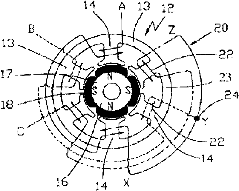
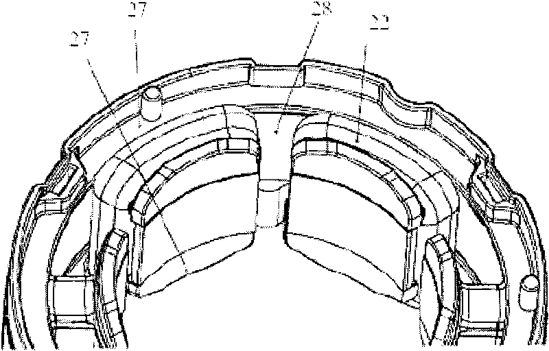
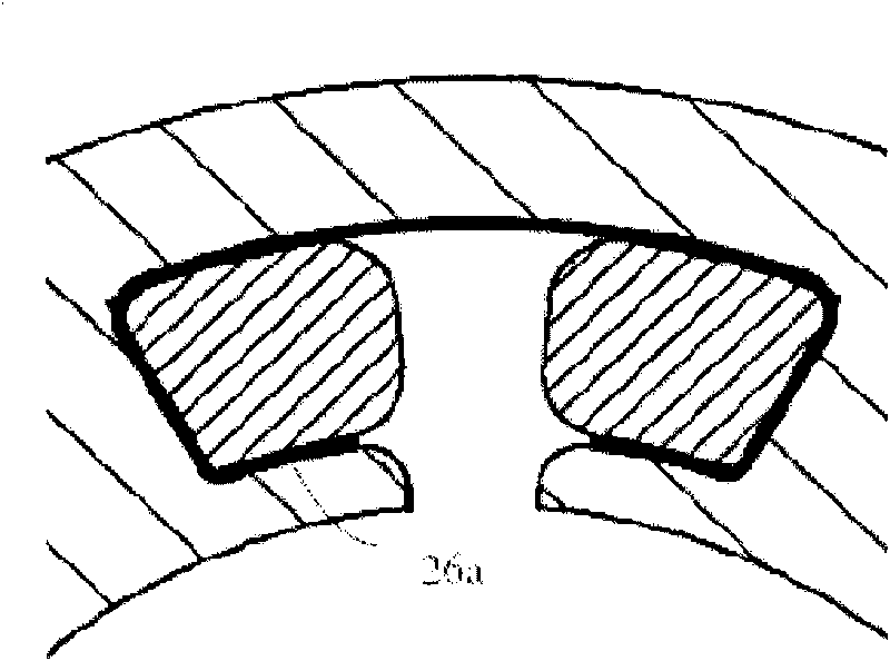
[0017] see Figure 4 to Figure 6 , the motor stator assembly 100 according to an embodiment of the present invention includes a stator core and a stator winding. The stator core is substantially cylindrical, and has six stator poles extending radially inward along the stator core, preferably, each stator pole is evenly spaced along the circumferential direction; the stator pole has a radially extending neck 112 and the pole piece 113 extending circumferentially at the end of the neck, the stator poles are connected by a yoke 114, two adjacent stator poles and the yoke connecting the two stator poles form a core groove 115. The core slot 115 has notches 116 formed by the pole shoes of the two stator poles. The stator windings form a coil 121 on each stator pole with slot insulation 130 lining the coil 121 and the corresponding stator pole electrically insulating the tw...


PUM


Abstract

The invention relates to the electric machine technology and provides an electric machine stator component. The component comprises a stator core and a stator winding wound on the stator core, wherein the stator core comprises a plurality of stator poles which are distributed along the circumference at intervals and extend along the radial direction and yokes used for connecting all stator poles together, the adjacent two stator poles and a yoke used for connecting the two stator poles constitute an iron core groove; and the stator winding is placed in the iron core grooves, groove insulation parts are lined between the stator core and the stator winding for electric insulation, an opening corresponding to the notch of one iron core groove is formed between the two end parts of each groove insulation part, and a flange is formed on the side with the opening of the end parts of the groove insulation part. The embodiment of the invention can increase the insulation performance between the stator core and the stator winding while the overall dimension of the stator component is not increased.

Description

technical field [0001] The invention relates to motor technology, in particular to a motor stator assembly and a motor. Background technique [0002] 1 and 2 show a schematic diagram of a three-phase brushless direct current (BLDC) motor in the prior art. The stator assembly 12 includes a stator core 13, a stator winding 20 and an insulating wire frame 27. The stator core 13 has a stator pole 14. , each stator pole 14 has a neck and a pole shoe, each stator pole is connected by a yoke 21, and an iron core groove 23 is formed between adjacent stator poles; the rotor assembly 16 has a magnetic pole 18, and the magnetic pole is mounted on The outer surface of the rotor core 17 is composed of permanent magnets. The stator winding 20 is formed on each stator pole 14. One end (A, B, C) of the coil 22 is connected to the stator end, and the other end (X, Y, Z) is connected to the stator end. connected to a common point 24, forming a star connection. The coils 22 and the respectiv...

Claims


Application Information

Patent Timeline
Patent Type & Authority Applications(China)
IPC IPC(8): H02K3/34H01B3/08H01B3/30H02K1/12
CPCH02K3/325H02K3/345
Inventor 储俊杰于惠芳
Owner JOHNSON ELECTRIC SHENZHEN
Why Eureka
Try Eureka