Valve part for a control valve for control of pressure medium flows

A pressure medium, control valve technology, applied in valve devices, multi-port valves, engine components, etc., can solve problems such as pressure imbalance

Active Publication Date: 2010-06-23
SCHAEFFLER TECH AG & CO KG
View PDF2 Cites 11 Cited by
  • Summary
  • Abstract
  • Description
  • Claims
  • Application Information

AI Technical Summary

Problems solved by technology

The consequence is that this effect first causes a pressure imbalance in the center of the control piston 102, which produces an undesired force curve for the required axial movement of the control piston 102

Method used


Image

  • Valve part for a control valve for control of pressure medium flows
  • Valve part for a control valve for control of pressure medium flows
  • Valve part for a control valve for control of pressure medium flows

Examples


Embodiment Construction

[0031] The electromagnetic control valve shown in FIG. 4 has been introduced in detail in the introduction of the specification according to the classification of traditional valve parts, so no further description will be made here.

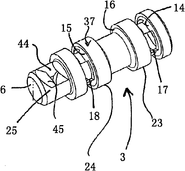
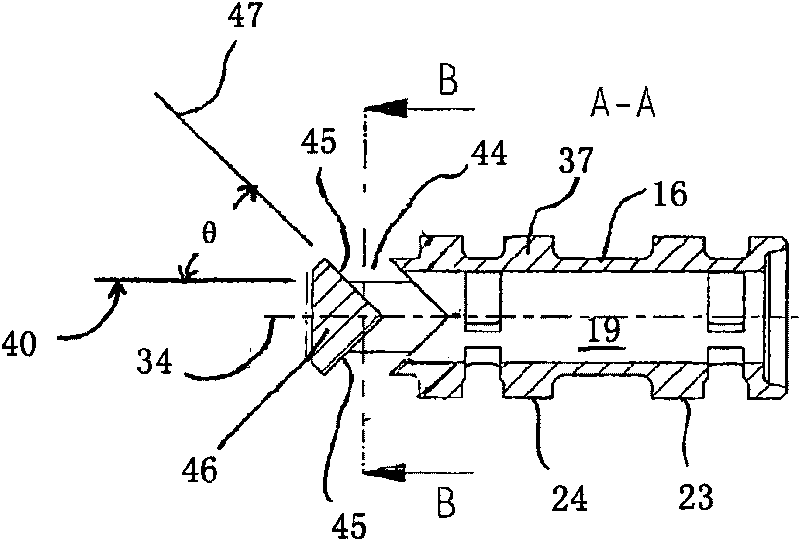
[0032] Figures 1 to 3 An exemplary embodiment of a valve element according to the invention for a solenoid control valve of a camshaft adjuster for an internal combustion engine is shown.

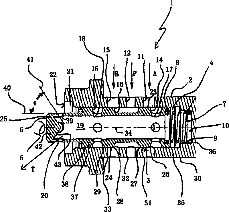
[0033] first observe figure 1 , wherein a first embodiment of the valve member according to the invention is shown in axial section. In particular a solenoid control valve for pressure medium regulation of a hydraulic camshaft adjuster of an internal combustion engine. The valve part 1, designated as a whole by the reference numeral 1, comprises a substantially hollow cylindrical valve housing 2, which has an axially (parallel A first cylinder outer section 35 on the cylinder axis 34 ) and a first cylinder base section 36 extending perpendicular to the cyli...


PUM


Abstract

The invention relates to a valve part for a control valve for control of pressure medium flows, comprising a cylindrical valve housing (2) with a first cylinder sleeve section (35) running in the axial direction and a first cylinder base section running perpendicular to the axial direction, defining a valve housing chamber (4) open at one end, wherein the first cylinder sleeve section is provided with a first working connector (A), a second working connector (B) and a pressure connector (P) which each open out in the valve housing chamber and a cylindrical control piston (3) housed in the valve housing chamber such a as to move axially with a second cylinder sleeve section running in the axial direction and a second cylinder base section running perpendicular to the axial direction, defining a control piston chamber which is open to one side, wherein the second cylinder sleeve section, adjacent to the second cylinder base section is provided with a radial outer connection (T) opening in the control piston chamber and the control piston is designed such that the working connections may be made with a fluid connection to pressure connector and the outlet connector by axial displacement of the control piston. The valve part is characterised in that the outlet connection of the control piston has at least one inclined opening, the wall direction of which has an angle of less than 90 DEG to the axial direction.

Description

technical field [0001] The invention relates to the technical field of control valves and according to its classification to an actuator-actuated valve part of a control valve for controlling a flow of a pressure medium according to the preamble of claim 1 . Background technique [0002] In internal combustion engines, the gas exchange valves are actuated by cams of a camshaft which is rotated by the crankshaft, wherein the actuation times of the gas exchange valves can be specified in a targeted manner through the arrangement and shape of the cams. In the context of thermodynamic processes, it has proven to be advantageous to influence the control time of the gas exchange valve during operation of the internal combustion engine as a function of the actual operating state, such as speed or load, via the connection between the camshaft and the crankshaft. The relative rotational position is predetermined. Devices generally known as "camshaft adjusters" have long been known f...

Claims


Application Information

Patent Timeline
Patent Type & Authority Applications(China)
IPC IPC(8): F16K11/07F01L1/34
CPCF01L2001/3443F16K11/0716F01L1/3442F01L2001/34426F16K11/0708Y10T137/86702
Inventor 约翰·施塔尔曼
Owner SCHAEFFLER TECH AG & CO KG
Why Eureka
Try Eureka