

Mandrel-holding device for tube mills
A clamping device and tube rolling mill technology, applied in metal rolling, metal rolling, metal processing equipment and other directions, can solve the problems of equipment damage, the clamping block can not effectively limit the mandrel swing, etc., to maintain stability , Guaranteed quality, small force arm effect
- Summary
- Abstract
- Description
- Claims
- Application Information
AI Technical Summary
Problems solved by technology
Method used
Image

Examples
Embodiment Construction
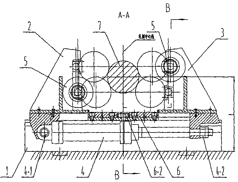
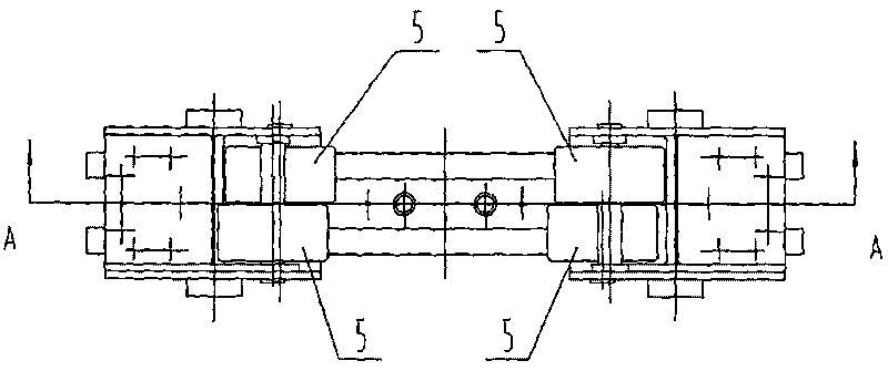
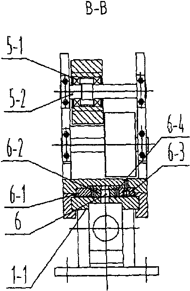
[0016] like figure 1 , 2 . As shown in 3, a mandrel clamping device for a pipe rolling mill includes: a base, an oil cylinder connected to the base through a moving mechanism, and a clamping piece driven by the oil cylinder through a moving mechanism. Described moving mechanism is made up of slide rail 1-1 and left slide seat 2, right slide seat 3, and described slide rail 1-1 is installed on the base 1, and described slide rail 1-1 is connected with left slide seat 2, right slide seat respectively. The bottom chute of slide seat 3 is connected, the left slide seat 2 is connected to the bottom earring of oil cylinder 4 arranged horizontally through pin shaft 4-1, and the piston rod thread of oil cylinder 4 is connected to right slide seat 3 through nut 4-2. The bottom of the bottom; the clamping member is a roller 5, there are four rollers 5, two of the rollers 5 are assembled on the left slide 2, and two of the rollers 5 are assembled on the right slide 3 Above, the instal...
PUM
 Abstract
Description
Claims
Application Information