
Anti-electrostatic crane tube telescopic oil drain device

An oil discharge device and anti-static technology, which can be used in distribution devices, special distribution devices, liquid distribution, transportation or transfer devices, etc., and can solve problems such as economic loss and personal injury, safety hazards of crane oil discharge pipelines, and easy generation of static electricity. , to achieve significant economic and social benefits, avoid economic losses and personal injury accidents, prevent burning and explosion effects

Inactive Publication Date: 2010-06-30
李军
View PDF0 Cites 5 Cited by
  • Summary
  • Abstract
  • Description
  • Claims
  • Application Information

AI Technical Summary

Problems solved by technology

[0002] At present, the crane pipe oil discharge pipeline of single well oil storage tank adopts rubber threaded pipe. After a certain period of use, the spiral steel wire in the rubber threaded pipe is easy to be exposed, and static electricity is easy to be generated when the oil tank truck entrance is contacted and rubbed, which is easy to ignite the tank Combustible gas can cause an explosion, resulting in major economic losses and personal injury accidents. Therefore, the existing crane pipe oil discharge pipeline has a relatively large safety hazard

Method used


Image

  • Anti-electrostatic crane tube telescopic oil drain device
  • Anti-electrostatic crane tube telescopic oil drain device
  • Anti-electrostatic crane tube telescopic oil drain device

Examples


Embodiment Construction

[0008] Embodiments of the present invention will be described below in conjunction with the accompanying drawings.

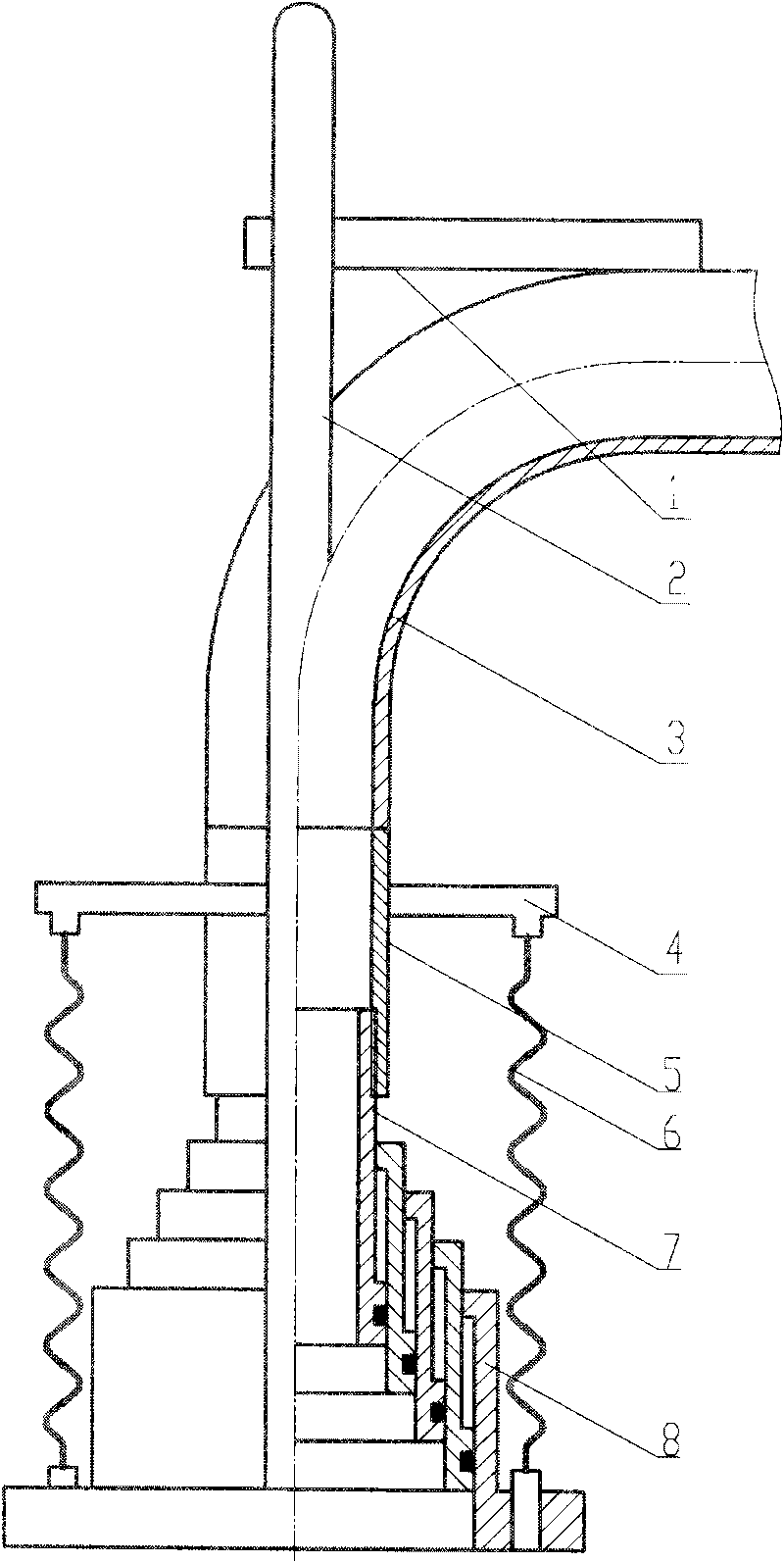
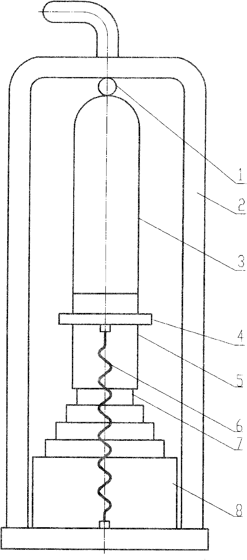
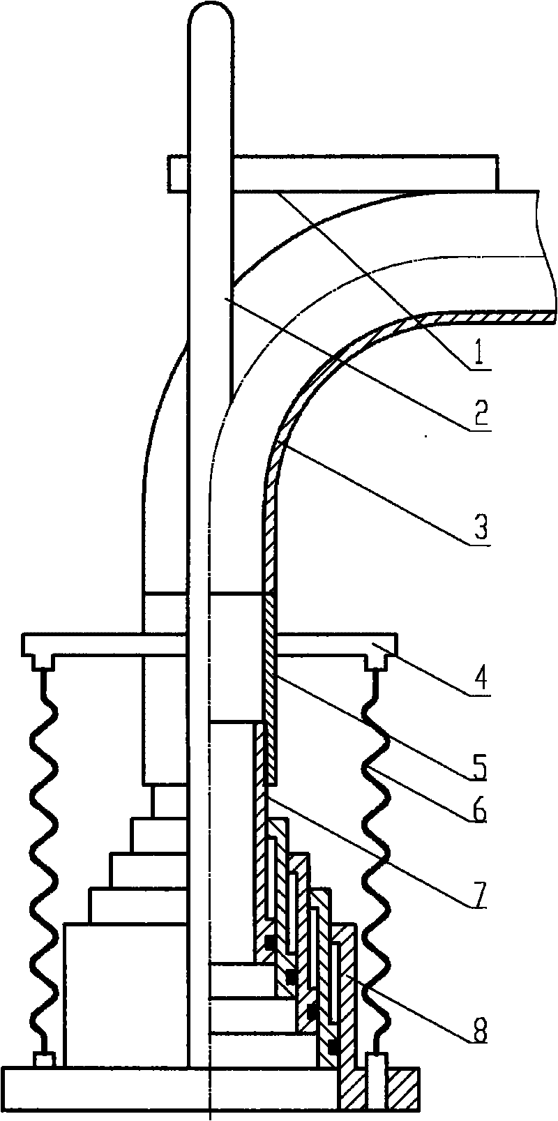
[0009] As can be seen from the figure, the embodiment of the present invention is composed of a hanging rod 1, a bracket 2, a crane tube 3, a spring frame 4, a connecting pipe 5, a spring 6, a fixed pipe 7, and a telescopic sleeve 8. The material of the telescopic sleeve 8 is nylon. The tube 5 is welded to the lower end of the crane tube 3, the fixed tube 7 is threadedly connected with the connecting tube 5, the lower end of the fixed tube 7 has a shoulder, and the telescopic sleeve 8 is composed of multi-stage mutual fittings, and the lower end of each telescopic sleeve 8 is provided with a shoulder, which is suspended from each other At the shoulder, the first-stage telescopic sleeve 8 is set outside the fixed pipe 7, and is suspended from the shoulder at the lower end of the fixed pipe 7. The lower end of the spring 6 is hung on the lower side of the lowermost...


PUM


Abstract

The invention relates to an anti-electrostatic crane tube telescopic oil drain device, nylon is taken as material of a telescopic sleeve, a connecting tube is welded at the lower end of a crane tube, a fixed tube is in threaded connection with the connecting tube, a shoulder is arranged at the lower end of the fixed tube, the telescopic sleeve consists of a plurality of levels by mutual sheathing, the shoulder is arranged at the lower end of each level of the telescopic sleeve, the plurality of levels of the telescopic sleeves are mutually hung at the shoulders, the first level of the telescopic sleeve is sheathed outside the fixed tube, the lower end of a spring is hung on the lower side outside the lowest level of the telescopic sleeve, the upper end of the spring is hung on a spring bracket, the spring bracket is welded on the connecting tube, the lower end of a support is fixed outside the lowest level of the telescopic sleeve, the upper end of the support is hung on a hanging rod, the hanging rod is fixed on the crane tube, a seal ring is mounted between each two levels of the telescopic sleeves, and the seal ring is mounted between the fixed tube and the first level of the telescopic sleeve. The plurality of levels of the telescopic sleeves are combined together and can contract and expand, thereby meeting the requirement on extending into an inlet of an oil pulling tank truck; and the telescopic sleeve is made of the nylon material, thereby avoiding producing static electricity when in contact with the inlet of the oil pulling tank truck, preventing combustion of combustible gas and explosion, and avoiding economic loss, personal injuries and accidents.

Description

technical field [0001] The invention belongs to equipment for transferring crude oil in an oil field, and is an oil discharge device installed on an oil storage tank, in particular to a telescopic oil discharge device for an antistatic crane tube. Background technique [0002] At present, the crane pipe oil discharge pipeline of single well oil storage tank adopts rubber threaded pipe. After a certain period of use, the spiral steel wire in the rubber threaded pipe is easy to be exposed, and static electricity is easy to be generated when the oil tank truck entrance is contacted and rubbed, which is easy to ignite the tank Combustible gas can cause an explosion, resulting in major economic losses and personal injury accidents. Therefore, there is a relatively large safety hazard in the existing crane pipe oil discharge pipeline. Contents of the invention [0003] The purpose of the present invention is to design a telescopic oil discharge device for anti-static crane pipes...

Claims


Application Information

Patent Timeline
Patent Type & Authority Applications(China)
IPC IPC(8): B67D7/42
Inventor 李军唐勇李利娟王风春
Owner 李军
Learn More