
Suspended combined hydraulic beaming device

A suspended, hydraulic technology, applied in mining equipment, earth-moving mining, pillars/supports, etc., can solve the problems of adding manual handling consoles, can not reduce the labor intensity of employees, increase the labor intensity of employees, etc., and achieve light weight. , easy operation, the effect of reducing labor intensity

Inactive Publication Date: 2010-06-30
刘卫平
View PDF0 Cites 2 Cited by
  • Summary
  • Abstract
  • Description
  • Claims
  • Application Information

AI Technical Summary

Problems solved by technology

[0003] There are currently two ways of raising the beam on site: one is to use the coal wall belly left in the excavation working face, and the operator stands on the coal wall belly to carry the beam with his hands and shoulders. The method requires a certain height of the coal wall belly to be reserved in advance. And because the softness of the coal walls is different, the safety and reliability of the workers standing on the beams on the coal walls is low, and a large amount of manpower is required to complete it, which increases the labor intensity of the workers
The second is to use round steel and steel plates to make a rectangular operating table in the excavation work face. Although it increases some safety, it increases the link of manual handling of the operating table, which still cannot reduce the labor intensity of the workers.
Constrained by the conditions of the excavation face during the beam raising period, there are certain hidden dangers of insecurity. At the same time, due to the concentration of personnel during the beam raising period, it is not conducive to the evacuation of personnel in case of an accident;
[0006] 2. The labor intensity of the workers is high
Currently 36U14m 2 The entire U-shaped steel beam weighs 144kg, and the U-shaped steel beam is a "three-centered arch" during the beam lifting period, making it difficult to manually lift the beam;
[0007] 3. Time-consuming and labor-intensive
[0008] 4. In the process of raising the beam, there is a great potential safety hazard due to the empty top operation above the head

Method used


Image

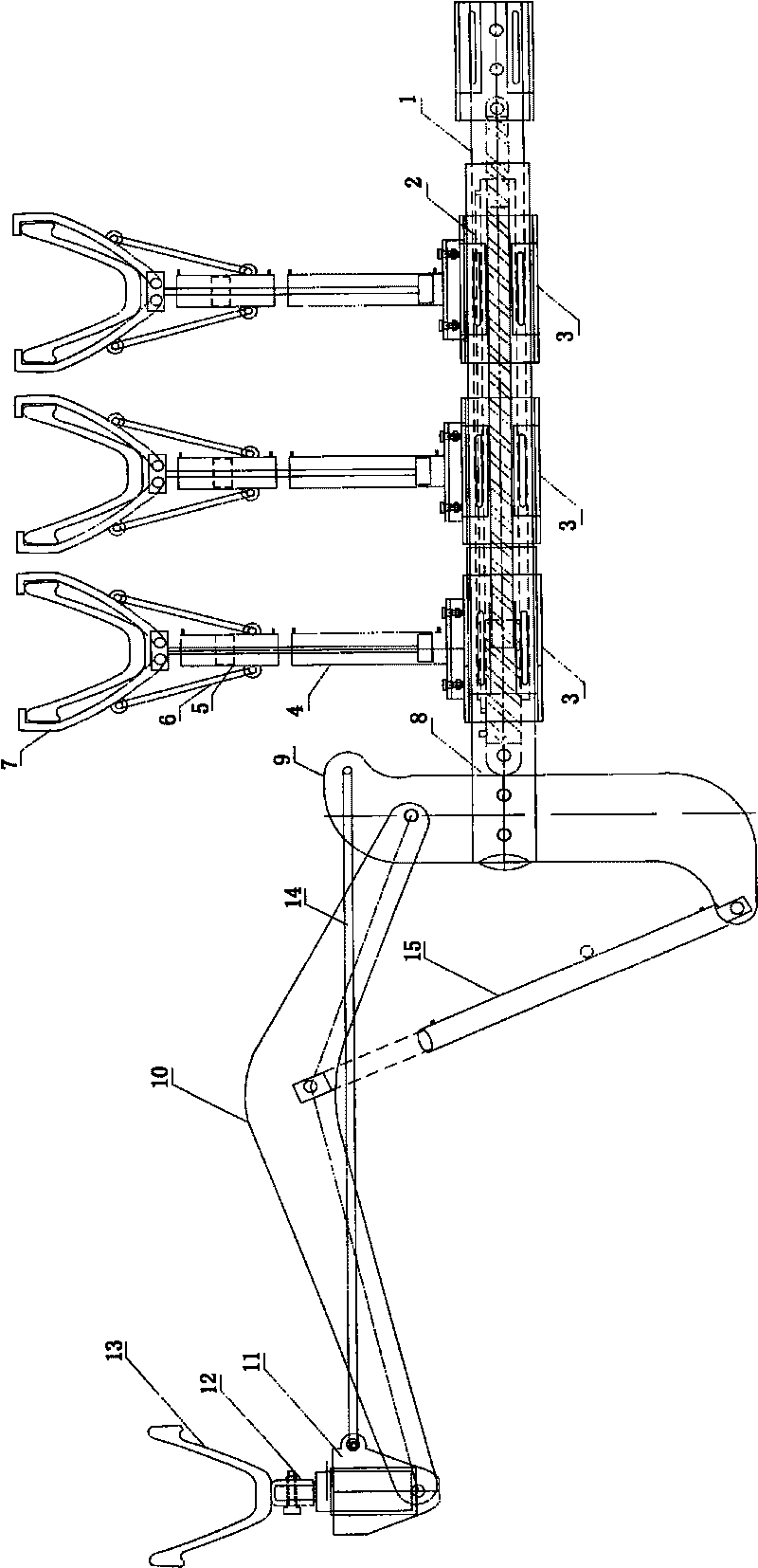
  • Suspended combined hydraulic beaming device
  • Suspended combined hydraulic beaming device

Examples


Embodiment Construction

[0025] The present invention will be further described below in conjunction with the accompanying drawings and specific embodiments, but not as a limitation of the present invention.

[0026] A preferred embodiment is given below:

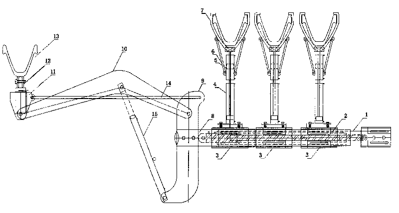
[0027] A suspended combined hydraulic beam upper device, comprising a main beam 1, on which a sub-beam 2 is arranged, and on the main beam 1, the upper part of the main beam bracket 3 is connected to the lifting cylinder 4 through a hanging hand grasping lifting cylinder 4. Hanging hand grasping oil cylinder 5, the hanging hand grasping oil cylinder 4 is connected to hanging hand grasping 7 through hanging hand grasping connecting rod 6, and the main beam supporting cover 3 is also connected with the main beam walking and Hanging arm walking oil cylinder 8; the end of the main beam 1 is provided with a joist arm seat 9, and the joist arm seat 9 is connected with a joist mechanism.

[0028] The joist mechanism comprises a joist arm 10 hinged at the...


PUM


Abstract

The invention relates to a beaming device, in particular to a suspended combined hydraulic beaming device, which is structurally characterized by comprising a main beam. The main beam is provided with a secondary beam; the upward side of a main beam support sleeve on the main beam is connected with a hanging grip cylinder by a hanging grip lift oil cylinder; the hanging grip cylinder is connected with a hanging grip by a hanging grip connecting rod; the main beam support sleeve is also connected with a main beam walking cylinder and a hanging arm walking cylinder which are arranged on the main beam; the end of the main beam is provided with a beam support arm seat; and the beam support arm seat is connected with a beam support mechanism. Compared with the prior art, the suspended combined hydraulic beaming device has the characteristics of reasonable design, simple structure, convenient operation, flexible and firm installation and the like.

Description

technical field [0001] The invention relates to a beam upper device, in particular to a suspended combined hydraulic beam upper device. Background technique [0002] At present, U-shaped steel support accounts for 95% of large-scale coal mine development, preparation, and recovery of coal seam roadways. 29U12m commonly used underground 2 and 36U14m 2 U-shaped steel bracket. 29U12m 2 The U-shaped steel bracket design is 4.4 meters wide, 3.2 meters high, and the length of the top beam is 3.954 meters. The weight of the entire beam is 116kg; 36U14m 2 The U-shaped steel bracket is designed to be 5.0 meters wide at the bottom, 3.4 meters high, and the length of the top beam is 3.958 meters. The weight of the entire beam is 144kg. [0003] There are currently two ways of raising the beam on site: one is to use the coal wall belly left in the excavation working face, and the operator stands on the coal wall belly to carry the beam with hands and shoulders to erect it. The meth...

Claims


Application Information

Patent Timeline
Patent Type & Authority Applications(China)
IPC IPC(8): E21D15/58
Inventor 邹山旺李洪山秦法秋别良涛王建伟刘际宏汪须堂刘传友张亚鹤朱玉杰戈光辉何宗权秦俊彬郭盛刘海君王国杰侯朝晖吴明森陈浩王萍邹辉庆黄栓劳郭青杰王明付
Owner 刘卫平
Learn More