
Scroll compressor

A technology for scroll compressors and compressor housings, which is applied to rotary piston machinery, rotary piston pumps, mechanical equipment, etc., and can solve the problems of increased axial clearance, increased vibration, and unstable movement of the cross ring. problems, to avoid leakage, reduce the effect of starting load

Active Publication Date: 2010-06-30
DALIAN SANYO COMPRESSOR
View PDF0 Cites 11 Cited by
  • Summary
  • Abstract
  • Description
  • Claims
  • Application Information

AI Technical Summary

Problems solved by technology

However, if the gap is too large, after the movable scroll moves to the fixed scroll, the axial clearance of the Oldham ring movement between the movable scroll and the upper support will increase, which will cause problems such as unstable movement of the Oldham ring and increased vibration.

Method used


Image

  • Scroll compressor
  • Scroll compressor
  • Scroll compressor

Examples


Embodiment Construction

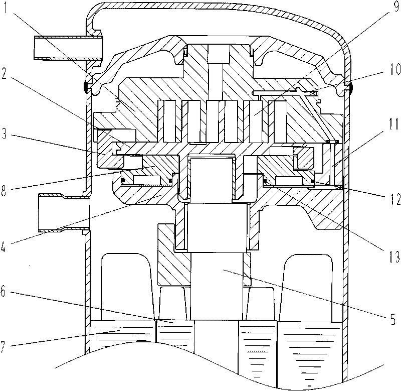
[0025] The present invention will be further described below in conjunction with the embodiments of the accompanying drawings. Such as figure 1 As shown, the scroll compressor mainly includes a fixed scroll 1 , a movable scroll 2 , an Oldham ring 3 , an upper support 4 , a crankshaft 5 , a motor rotor 6 , and a motor stator 7 . The fixed scroll 1 and the movable scroll 2 cooperate to form a plurality of compression chambers 9, and the cross ring 3 is arranged on the back side of the movable scroll 2 to cooperate with the fixed scroll 1 and the movable scroll 2, so that the movable scroll 2 can only be opposite to each other. The fixed scroll 1 moves in translation, the crankshaft 5 is driven by the motor stator 7 through the motor rotor 6, and the crankshaft 5 drives the movable scroll 2 to move along the orbital plane, thereby completing the suction, compression and exhaust process of the compressed working medium.

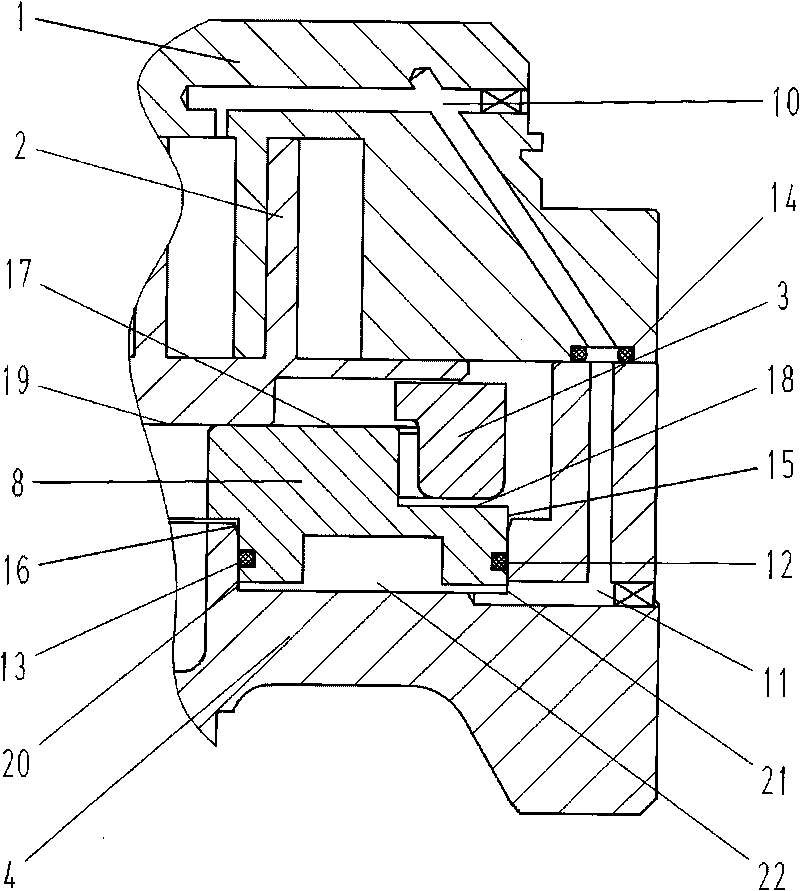
[0026] Such as figure 2 As shown, a floating disc 8 is p...


PUM


Abstract

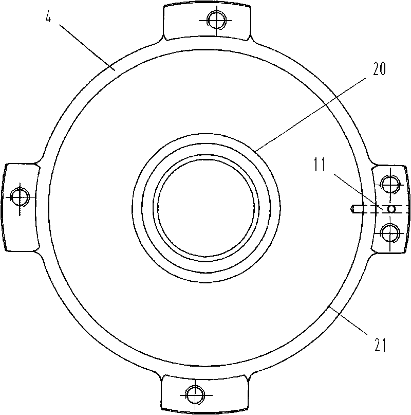
The invention discloses a scroll compressor. A floating disc is arranged between a movable scroll and an upper supporter of the compressor, the floating disc is a circular disc with two layers of steps, a crossed ring is positioned between the movable scroll and the upper surface of the second step of the circular disc of the floating disc, pressure guide passages are arranged on the upper supporter and the fixed scroll, and the pressure guide passages are communicated with a compression cavity of the compressor and the lower surface of the floating disc for forming a sealed cavity between pressure guide passages and the bottom surface of grooves formed on the upper supporter. The invention has the advantages that all sealing parts adopt static sealing, good and reliable sealing can be realized, the crossed ring moves flatly between the movable scroll and the step surface of the floating disc, the fit gap of the flat movement maintains unchanged, the problems of moving stability loss, vibration enhancement and the like of the crossed ring can not occur, the sealing effect of the sealing between the floating disc and the upper supporter can be ensured during large axial displacement, the movement gap of the crossed ring can not be changed after the floating of the movable scroll, the distance between the movable scroll and a fixed scroll can be longer, and the starting load can be reduced to the maximum degree.

Description

technical field [0001] The invention relates to the field of scroll compressors, in particular to a tooth top sealing structure of a scroll compressor. Background technique [0002] The existing scroll compressor includes a fixed scroll with a spiral scroll, a movable scroll with a spiral spiral matched with the fixed scroll, and a moving scroll between the movable scroll and the upper support. , which respectively cooperate with the movable and fixed scrolls and limit them to be relatively translational. Multiple compression chambers with variable volumes are formed through the mutual cooperation of the movable and fixed scrolls. The motor drives the crankshaft to drive the movable scroll. It revolves along its orbit to complete the suction, compression and discharge of gas. In order to improve the efficiency, it is necessary to make the volute crests of the two volutes fit closely with the tooth bottoms of the other volute so as to reduce the leakage of the crests between...

Claims


Application Information

Patent Timeline
Patent Type & Authority Applications(China)
IPC IPC(8): F04C18/02
Inventor 郑星张铁良周英涛朗贤明
Owner DALIAN SANYO COMPRESSOR
Learn More