Magneto-rheological damper of inbuilt displacement sensor

A magnetorheological damper, displacement sensor technology, applied in the direction of shock absorber, shock absorber, spring/shock absorber, etc., can solve the problem of not being able to directly provide a magnetorheological damper to the control system, and achieve a simple structure. Effect

Active Publication Date: 2010-06-30
CHONGQING MATERIALS RES INST
View PDF0 Cites 20 Cited by
  • Summary
  • Abstract
  • Description
  • Claims
  • Application Information

AI Technical Summary

Problems solved by technology

[0003] Aiming at the deficiency that the ordinary magnetorheological damper cannot directly provide the piston displacement signal in the magnetorheological damper to the control system, the present invention proposes a magnetorheological damper with a built-in displacement sensor, and a magnetorheological damper with a built-in displacement sensor The damper is realized by changing one of the piston rods into a tube shape and placing it inside the working cylinder on the basis of the ordinary double-rod magneto-rheological damper, and installing a displacement sensor in the tube; therefore, the magneto-rheological damper with the built-in displacement sensor The rheological damper not only has the adjustable damping force like the ordinary magnetorheological damper, but also provides the control system with the real-time displacement signal of the piston in the magnetorheological damper through the built-in displacement sensor.

Method used


Image

  • Magneto-rheological damper of inbuilt displacement sensor
  • Magneto-rheological damper of inbuilt displacement sensor

Examples


Embodiment Construction

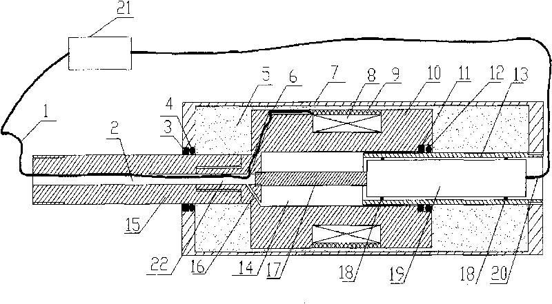
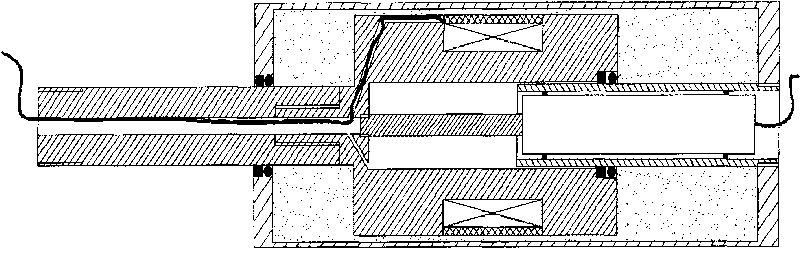
[0009] The structure of the present invention is described in detail below in conjunction with accompanying drawing:

[0010] see figure 1 , which is a specific structure of the present invention, one end of the built-in tube 13 made of non-magnetic metal material is fixed on the bottom of the working cylinder 7 by threads, and the other end of the built-in tube 13 is sealed by the mouth of the large hole 14 of the piston. Ring 12 and bearing 11 stretch in the large hole 14 of piston; Displacement sensor 19 is installed in the built-in pipe 13 by fixing ring 18, and the sliding shaft 17 of displacement sensor 19 is installed in the small hole 22 of piston large hole 14 bottoms by thread. The other end of the piston 10 made of high magnetic permeability metal material is connected to the piston rod 15 through threads. The piston rod 15 also has a central hole 2 and communicates with the small hole 22 of the piston 10 and the vent hole 16 . The middle part of the piston 10 is w...


PUM


Abstract

The invention discloses a magneto-rheological damper of an inbuilt displacement sensor, which is composed of a working cylinder, a piston of which the core is provided with big and small pores, a piston rod, an inbuilt pipe and a displacement sensor, wherein the working cylinder is filled with magneto-rheological fluid; when the piston rod pushes the piston to move in the working cylinder, the inbuilt pipe enters or retracts from the big pore of the piston while the piston rod enters or retracts from the working cylinder; because the external diameter of the piston rod is same with that of the inbuilt pipe, the volume of the working cylinder is constant; the movement of the piston drives a sliding axle of the displacement sensor arranged in the inbuilt pipe to move, so that the displacement sensor arranged in the inbuilt pipe can output the signal of piston real-time displacement amount.

Description

technical field [0001] The invention belongs to a magnetorheological damper, in particular to a magnetorheological damper with a built-in displacement sensor. Background technique [0002] Magneto-rheological damper is an intelligent damping device, its damping force can be adjusted steplessly by adjusting the current entering the electromagnetic coil in the magnetorheological damper; in practical applications, the control of magnetorheological damper When the system adjusts the damping force of the magnetorheological damper, in addition to referring to the moving speed and acceleration of the piston in the magnetorheological damper, it also needs to refer to many factors such as the displacement of the piston in the magnetorheological damper to adjust the magnetic flow. The damping force of the variable damper is adjusted in real time. Therefore, when using an ordinary magnetorheological damper, a displacement sensor is usually installed outside the magnetorheological dampe...

Claims


Application Information

Patent Timeline
Patent Type & Authority Applications(China)
IPC IPC(8): F16F9/53F16F9/50
Inventor 谭和平
Owner CHONGQING MATERIALS RES INST
Why Eureka
Try Eureka