
Method for removing photoresist and method for manufacturing connecting hole

A manufacturing method and technology of photoresist, applied in semiconductor/solid-state device manufacturing, photosensitive material processing, electrical components, etc. Effect of eliminating photoresist residue defects

Inactive Publication Date: 2012-01-25
SEMICON MFG INT (SHANGHAI) CORP
View PDF1 Cites 0 Cited by
  • Summary
  • Abstract
  • Description
  • Claims
  • Application Information

AI Technical Summary

Problems solved by technology

[0005] However, the above method for removing photoresist removes the photoresist layer through an inductively coupled plasma reaction process, and it is often difficult to remove the photoresist completely, and there will be photoresist residues on the substrate surface
Especially in the manufacturing process of trenches and / or contact holes of dual damascene structures, it is often necessary to use fluorine-containing gases as etching gases, such as CF 4 、C 4 f 6 , when performing etching with the above-mentioned gas plasma, the plasma will interact with the photoresist to form a difficult-to-remove polymer hard film on the surface of the photoresist, which is difficult to remove and will cause residual Physical defects

Method used


Image

  • Method for removing photoresist and method for manufacturing connecting hole
  • Method for removing photoresist and method for manufacturing connecting hole
  • Method for removing photoresist and method for manufacturing connecting hole

Examples


Embodiment Construction

[0038] The specific embodiments of the present invention will be described in detail below in conjunction with the accompanying drawings.

[0039] In the following description, numerous specific details are set forth in order to provide a thorough understanding of the present invention. However, the present invention can be implemented in many other ways different from those described here, and those skilled in the art can make similar extensions without violating the connotation of the present invention, so the present invention is not limited by the specific implementations disclosed below.

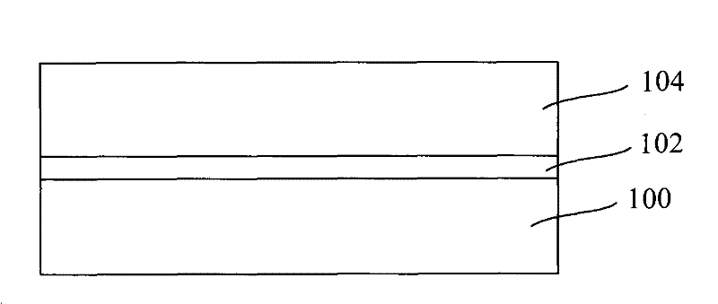
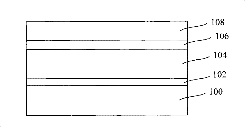
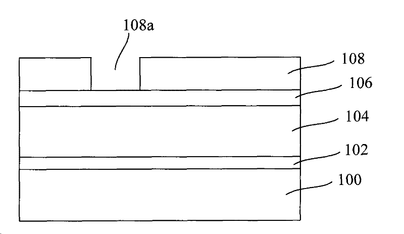
[0040] Secondly, the present invention is described in detail using schematic diagrams. When describing the embodiments of the present invention in detail, for the convenience of explanation, the cross-sectional view showing the device structure will not be partially enlarged according to the general scale, and the schematic diagram is only an example, and it should not be limited here. ...


PUM


Abstract

The invention discloses a method for removing photoresist, comprising the steps of providing a substrate with a photoresist layer; implementing plasma pretreatment on the photoresist layer; and removing the photoresist layer after the plasma pretreatment, wherein the plasma pretreatment is reactive ion etching process. The invention also provides a manufacturing method of a connecting hole. The invention can reduce or eliminate the defect of photoresist residue.

Description

technical field [0001] The invention relates to the technical field of semiconductor manufacturing, in particular to a method for removing photoresist and a method for manufacturing connection holes. Background technique [0002] In the semiconductor manufacturing process, it is necessary to form a photoresist pattern on the semiconductor substrate by photolithography, define a region to be processed in advance, and then perform etching or ion implantation according to the photoresist pattern. The level and quality of photolithography process directly affect the results of etching or ion implantation. [0003] In the photolithography process, the photoresist is first uniformly spin-coated on the surface of the semiconductor substrate by spin-coating, and then through a series of processes such as baking (bake), exposure (exposure), development (develop) and so on. The pattern on the film plate is transferred to the photoresist on the surface of the semiconductor substrate t...

Claims


Application Information

Patent Timeline
Patent Type & Authority Patents(China)
IPC IPC(8): G03F7/42H01L21/768H01L21/311
Inventor 沈满华陈海华韩宝东张海洋
Owner SEMICON MFG INT (SHANGHAI) CORP
Learn More