
Self-locking knob switch

A knob switch, self-locking technology, applied in electrical switches, electrical components, circuits, etc., can solve the problems of inability to play a locking effect, poor locking effect, easy to wear, etc., to avoid instability, avoid loss and effect of accident

Inactive Publication Date: 2010-06-30
OCEANS KING LIGHTING SCI&TECH CO LTD +1
View PDF0 Cites 20 Cited by
  • Summary
  • Abstract
  • Description
  • Claims
  • Application Information

AI Technical Summary

Problems solved by technology

However, the disadvantage of this structure is that the knob is screwed to the convex hull when it is closed, and it is screwed to the shell surface without convex hull when it is open. The convex hull is mostly made of plastic material, which is easy to wear after friction back and forth, and finally locked. The effect gradually deteriorates and cannot play the proper locking effect

Method used


Image

  • Self-locking knob switch
  • Self-locking knob switch
  • Self-locking knob switch

Examples


Embodiment Construction

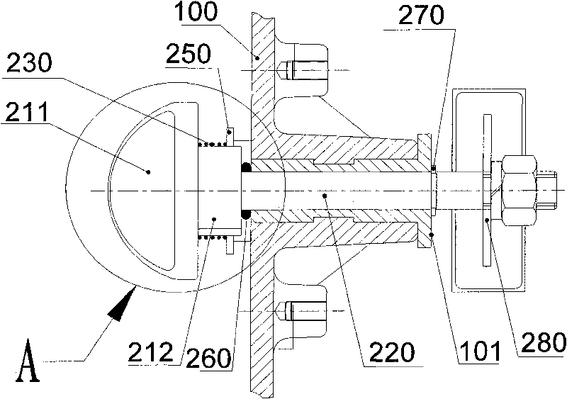
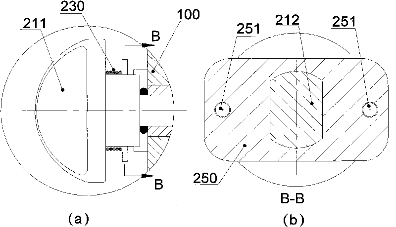
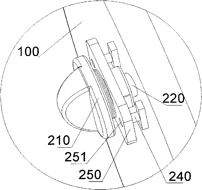
[0024] Such as figure 1 , figure 2 , image 3 As shown, the self-locking knob switch in the preferred embodiment of the present invention includes a knob 210 , a connecting rod 220 , a spring 230 , a protrusion 240 , and a locking piece 250 . Wherein, the knob 210 includes a handle portion 211 which is convenient for hand-held operation, and a connection portion 212 which has an insertion hole inside to facilitate connection with one end of the connecting rod 220 .

[0025] The entire self-locking rotary switch is installed on the housing 100 of a device, and the knob 210 is exposed on the outer surface of the housing 100 . The connecting rod 220 is perpendicular to the part of the housing 100 where it is located, and one end is fixedly connected to the knob 210 so as to be driven by the knob 210 to rotate, and the other end is equipped with a toggle piece 280 for triggering the internal switch by rotating different angles to realize the control of the device. operate. Wh...


PUM


Abstract

The invention relates to a self-locking knob switch comprising a knob (210) exposed outside a shell (100) and a connecting rod (220) which is perpendicular to the surface of the shell (100) and is installed in the shell (100), wherein one end of the connecting rod (220) is fixed with the knob (210) so as to rotate along therewith. The self-locking knob switch also comprises a projection (240) fixed on the external surface of the shell (100), a locking piece (250) which is sheathed on and rotates along with the knob (210) and a spring (230) with one end connected with the knob (210) and the other end contacted with the locking piece (250), a concave hole (251) matched with the projection (240) is arranged on the locking piece (250), and the locking piece (250) is pressed onto the projection (240) by the spring (230). The self-locking knob switch is constrained by the axial pressing force of the spring and the radial matched limit of the projection and the locking piece and can prevent equipment from being opened under accidental impact or misoperation of operating personnel, thereby avoiding accidental loss and incidents.

Description

technical field [0001] The present invention relates to a switch, more specifically, to a self-locking knob switch. Background technique [0002] Knob switch is a very common switch form in daily life, that is, the device is operated by rotating the knob, such as adjusting the device to the working state of on or the stop state of off. The knobs are all set outside the device housing for easy operation, while the actual switch is inside the device. There is a connecting rod connected between the switch and the knob. Rotating the knob drives the connecting rod to trigger the on / off state of the switch. [0003] If the equipment is turned off or turned on under abnormal conditions, it is easy to cause failures or accidents, so it should be avoided, and controlling the knob switch is an important part of it. Because the knob is exposed outside the shell, it is easy to be accidentally driven to rotate due to external sudden impact or misoperation. For example, continuous bumpin...

Claims


Application Information

Patent Timeline
Patent Type & Authority Applications(China)
IPC IPC(8): H01H19/03
Inventor 周明杰林群
Owner OCEANS KING LIGHTING SCI&TECH CO LTD
Learn More