A shift register circuit having threshold voltage compensation

A shift register and threshold voltage technology, applied in static memory, digital memory information, instruments, etc., can solve problems such as transistor performance degradation and limited circuit life

Inactive Publication Date: 2010-06-30
KONINKLIJKE PHILIPS ELECTRONICS NV
View PDF1 Cites 39 Cited by
  • Summary
  • Abstract
  • Description
  • Claims
  • Application Information

AI Technical Summary

Problems solved by technology

[0011] The problem remains with known circuits that degradation of transistor performance, especially for transistors operating at high duty cycles and thus normally on, limits the lifetime of the circuit

Method used


Image

  • A shift register circuit having threshold voltage compensation
  • A shift register circuit having threshold voltage compensation
  • A shift register circuit having threshold voltage compensation

Examples


Embodiment Construction

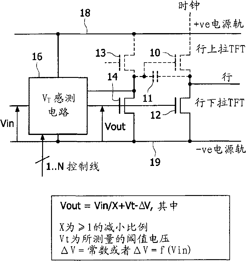
[0060] figure 1 A first simplified example of the inventive circuit is shown to illustrate the principles of the invention.

[0061] The present invention provides sensing of the threshold voltage of the most critical transistor or transistors in the circuit. The row driver circuit has: a row pull-up transistor 10, which is turned on to provide a row pulse on the row from the clocked power supply line "CLOCK"; and a row pull-down transistor 12, which is used on the remaining Time keeps the row at a low negative power rail voltage. Row pull-down transistor 12 operates at a high duty cycle and therefore suffers from the greatest drift.

[0062] In one example, the present invention provides threshold voltage sensing of the row pull-down transistor 12 . The sensing circuit may use thin film transistors (TFTs) of the row driver circuit, or it may use dedicated TFTs designed to match the characteristics of the TFT being compensated.

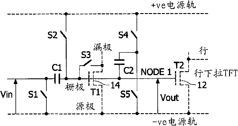
[0063] figure 1 Transistor 14 for replicat...


PUM


Abstract

A shift register circuit comprises a plurality of stages, each stage being for providing an output signal to an output load and comprising a pull up transistor for pulling the output signal up to a high voltage rail and a pull down transistor for pulling the output signal down to a low voltage rail. Each stage comprises a circuit for sampling the threshold voltage of at least one of the pull up and pull down transistors and for adding the sampled threshold voltage to a control voltage offset, to provide a threshold- voltage-compensated signal for controlling the gate of the at least one of the pull up and pull down transistors. This provides threshold voltage sampling, in particular for the thin film transistor whose threshold voltage drift must be compensated (for example the pull-down thin film transistor).

Description

technical field [0001] The present invention relates to a shift register circuit, in particular a shift register circuit for supplying row voltages to display pixels of an active matrix display device. Background technique [0002] An active matrix display device includes an array of pixels arranged in rows and columns, and each pixel includes at least one thin film drive transistor and a display element such as a liquid crystal cell. Each row of pixels shares a row conductor connected to the gates of the thin film transistors of the pixels in that row. Each column of pixels shares a column conductor to which pixel drive signals are provided. A signal on the row conductor determines whether the transistor is turned on or off, and when the transistor turns on (by a high voltage pulse on the row conductor), the signal from the column conductor is allowed to pass to the area of ​​the liquid crystal material, thereby changing the light in that material. transmission properties...

Claims


Application Information

Patent Timeline
Patent Type & Authority Applications(China)
IPC IPC(8): G09G3/36G11C19/18
CPCG09G3/3677G11C19/184
Inventor E·博伊科
Owner KONINKLIJKE PHILIPS ELECTRONICS NV
Why Eureka
Try Eureka